Have you separated the Signal Ground from the Audio Ground/Power Ground/Chassis Earth?
input signal ground from POT is connected to a common ground point of NFB, IC and input coupling then -> with a distance of 3cm connection to amplifier's bypass cap's ground(input ground point for amplifier board).
Amplifier ground point is connected to another common ground point which is next to psu filter cap board. Speaker's ground connected to this point too.
Earth is connected to chassis only, there is no connection between Earth and circuit ground.
?mVdc is the DC output offset. 0.1mVdc is a very good low value.
?mVac is the AC output signal. This comprises: amplifier noise + input source noise + distortion + interference.
If the source is set to send zero signal level then 10mVac signal at the output is absolutely terrible.
You should be aiming for <<1mVac.
?mVac is the AC output signal. This comprises: amplifier noise + input source noise + distortion + interference.
If the source is set to send zero signal level then 10mVac signal at the output is absolutely terrible.
You should be aiming for <<1mVac.
Reduced the power ground wiring from 50cm to 25cm, no changes to the 50Hz hum volume.
Measured Audio ground with respect to PSU ground. 000.0mVac and 000.0mVdc.
Measured inverting(12mVac/0mVdc) and non-inverting(17mVac/0mVdc) inputs with respect to PSU ground.(POT at highest position)(no source)
Measured inverting(4.5mVac/0mVdc) and non-inverting(4.5mVac/0mVdc) inputs with respect to PSU ground.(POT at any position)(sound card with Buffer output).
Hi cent88.
If you have a hum on the output, it could be ground loops and AndrewT and myself were discussing on another thread.
I cured mine by separating Earth, Power ground and signal ground with a resistor and 2 diodes. You connect Main Earth to Power Ground with a 10 ohm resistor and 2 diodes back to back, and then the same for the power ground to signal ground.
Like this:
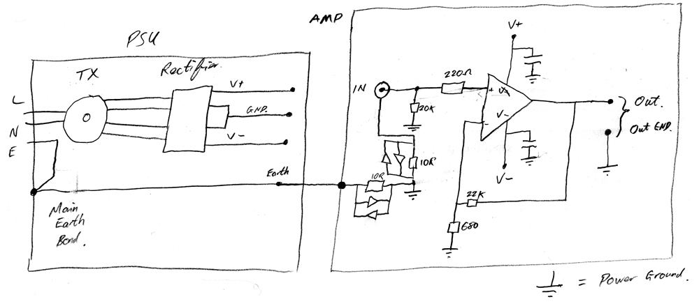
Obviously the GND from the PSU is connected in the amp to the Power Ground")
I also had a popping sound after I turned off the amp. I think it was AndrewT who suggested putting a 330pF cap across the inputs + and - of the amp. This worked fine.
If you have a hum on the output, it could be ground loops and AndrewT and myself were discussing on another thread.
I cured mine by separating Earth, Power ground and signal ground with a resistor and 2 diodes. You connect Main Earth to Power Ground with a 10 ohm resistor and 2 diodes back to back, and then the same for the power ground to signal ground.
Like this:
Obviously the GND from the PSU is connected in the amp to the Power Ground
I also had a popping sound after I turned off the amp. I think it was AndrewT who suggested putting a 330pF cap across the inputs + and - of the amp. This worked fine.
Last edited:
two diodes in parallel but one inverted relative to the other (inverse parallel). These will pass current in both directions................... and 2 diodes back to back, ................
Back to back diodes will not pass current in either direction.
What is shown in the schematic for inverse parallel is correct.
Port,
The feedback connection at the bottom of 680r does not go to Power Ground.
It returns to Signal Ground, i.e. to the top end of the upper 10r.
Think of the amplifier symbol's +IN & -IN as two inputs. The amplifier measures the voltage between the two inputs and tries to output a scaled copy of this voltage.
The amp RCA input is what you want the amplifier to copy and scale. The feedback must which is directly connected to the -IN input MUST connect to the wanted signal.
Last edited:
Hi Andrew, just noticed I also have the 22k input resistor connected to power ground, not signal ground. (MY actual amp is wired correctly)
Anyway, here is the amended schematic:
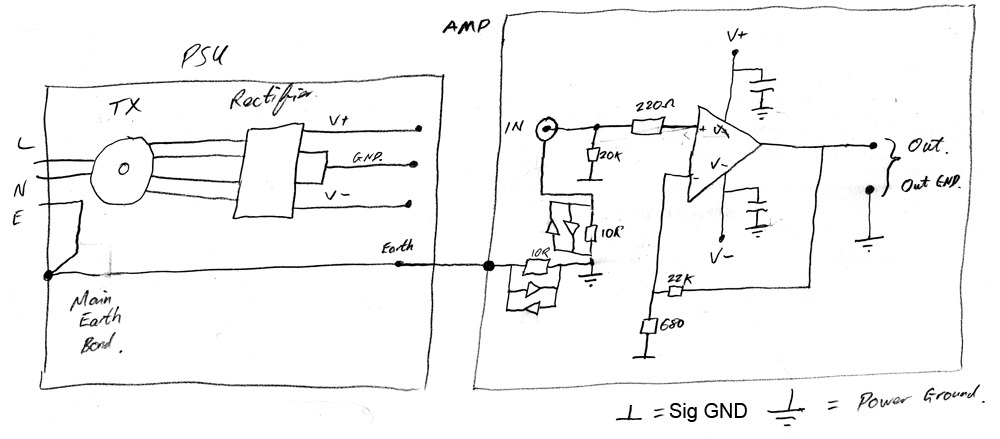
I have a question. The LM3875 amp I made is all in one enclosure, the drawing above shows a separate PSU and Amp enclosure. If you were to use 1 PSU enclosure to feed 2 or more amp enclosures, would you wire each amp enclosure as per the drawing or would you connect the main earth to power ground (via the resistor and diodes) in the PSU?
Anyway, here is the amended schematic:
I have a question. The LM3875 amp I made is all in one enclosure, the drawing above shows a separate PSU and Amp enclosure. If you were to use 1 PSU enclosure to feed 2 or more amp enclosures, would you wire each amp enclosure as per the drawing or would you connect the main earth to power ground (via the resistor and diodes) in the PSU?
Last edited:
With a "buzz" it sounds like a wide-band 60 Hz with lots of harmonics. That could be a ground loop, but suggests to me something else.
What about the rectifier? Put a 0.1uF capacitor (with rated voltage higher than the p-p secondary output voltage, of course) across each rectifier diode. You can do this even if the rectifier is one full-wave bridge package with four wires coming out: put a cap from each of the two AC terminals to each of the + and - terminals (that's four capacitors). If this eliminates the buzz or reduces it substantially, that's your major problem. If it only "substantially reduces" it, it could need better snubbing (with R-C instead of just C) or the remaining hum or buzz could be caused from something else.
I've seen this discussed several times in other threads here - snubbing the rectifier diodes should be standard practice in the power supply of any mains-operated audio device.
I find the back-to-back diodes between signal and Earth ground a little bit dodgy (I've read threads on this practice before). I'd want to put about a .01uF capacitor across the diodes to prevent RF rectification that might suddenly show up in the audio if (for example) a CB radio transmits nearby. This will increase
Page 1 of this document tells one way that hum can get into an audio system between an amplifier and another device (computer, CD player, line-powered tuner) that also plugs into the power line. The fact that you have a buzz with nothing plugged in to the input or when using a battery-operated device such as an iPod suggests the problem is not (or is in addition to) this problem:
http://www.jensen-transformers.com/an/an004.pdf
- Status
- This old topic is closed. If you want to reopen this topic, contact a moderator using the "Report Post" button.
- Home
- Amplifiers
- Chip Amps
- New built LM3886 buzz