sam9 said:I think the MPS8099s will limit you to 38V in the IS, at least if you want to use devices that are safe even if exposed to the total rail-to-rail potential. MPSA42/92 would take care of that problem. In fact you could then simplify things by having a single set of rails.
Since we don't know what the rail voltages are and we don't know exactly what current the input pair runs at, we must do a little analysis. I assume +-50v or so for the rails (100 watt output), and guess about 2ma for the pair (giving about a match for the 4 diode drop on the VAS emitter, assuming that should be equal to the voltage across the 3K0 load resistors).
For the input pair, you want the highest beta lowest noise parts you can use, which is not usually consistent with high breakdown voltage. What is really needed here? The input pair sees only half the rail to rail voltage (unless something is broken). The bases are tied to ground through low resistances, and with the currents I assumed they will be very close 0v.
For best performance I would try a 60v dual transistor. You can certainly leave the MPS8099s since their 80v rating is adequate and they have decent characteristics otherwise. The next step would be the 150v devices like the 2n5401/2N5551, with slightly worse parameters. The MPSA42/92 pair has low beta and I would not use them unless the rail voltages were much higher.
The Peasant said:Hello everyone,
I feel that a separate regulated power supply for the driver circuitry is very important and results in a more stable and better sounding amplifier. This may be why this type amplifier works well with the difficult impedances and current demands of the electrostatic speakers. How do others feel about this?
Doug")
I would absolutely go for the regulated power supply for the driver. A simple RC filter will not be as efficient. I had an amplifier having already the RC (10 ohms and 100uF) along with a series diode but when I have added before it a series regulator, the improvement was quite noticeable. See my thread discussing this subject "DH-200/200 mods" for more details.
"The MPSA42/92 pair has low beta and I would not use them unless the rail voltages were much higher."
Good point. However the beta isn't quite as low as the minimum figures on the data sheet, I just check a batch I had and they were all about 70 which may or may not be sufficient. What I likew about them is their consistancy. At least from my supplier I can get usually get an exact beta match with in about the first four pieces. I just check my latest batch of ten, the range was approximately 68-73. My experience with 2n5551/2n5401 is that the range is much greater in a typical batch. Also the MPS's seem to be more consistent between batches.
Nonetheless, I use a lot of 2n5551/2n5401 as well.
sam9 said:" My experience with 2n5551/2n5401 is that the range is much greater in a typical batch. Also the MPS's seem to be more consistent between batches.
Nonetheless, I use a lot of 2n5551/2n5401 as well.
So far the 2N5551 and 2N5401 I have found had almost all beta between 100 and 140. Of course, you may have to buy a few to get matched beta. I allow up to 20% difference between them for input pairs and I am still able to get less than 10 mv DC offset at amplifier output without any resistor adjustment or DC servo (in 3 amps).
thanh said:value of input capacitor should be 470uF!
And why is that??? f0 (the input cap here acts as a RC hipass filter) is low enough with 8uf...
"value of input capacitor should be 470uF!"
470uF will either be an electolytic or a film cap as big as the rest of the PCB. So I assume it is an electro. Now, I was aware that electros don't have infinite bandwidth but I didn't realize how significant that might be until the other day I re-read (browsed) an old JL Hood book. In it he presented the series resistance of a 470uF electro as an example. The series resistance starts rising sharply around 10kHz - thus using a 470uF will not be a high-pass but a band-pass filter!!
The highs dies!
If you insist on such a value you really need to parallel it with a small value cap. Oddly enough I've noticed that the electro models in LTspice don't account for this -- another case where Spice can lead you astray.
"value of input capacitor should be 470uF!"
Other reasons to go with a big value here (assuming that it is in parallel with other lower value of better capacitor types):
1- several pre-amps have capacitors (unknown value) at their output (in series with their amp output). This capacitors appears in series in some respect with the input cap of the power amp. Series means lower effective value at input power amp, thus higher low frequency cut-off. With a value like 100uf or more, the power amp becomes less dependent of the pre-amp it is connected to (if pre-amp has really an output cap).
2- Having a very low low frequency cut-off at input of power amp prevents high phase shift of the signal at 20 Hz.
As I wrote in another thread I once discovered that a 70's (80's?) era reciever claimed an "intgrated rumble filter" (or maybe the adjective was "automatic") that was nothing but a 2uF cap on the input!!
Anyway one advantage of DIY is that you know and can choose what's in your equipment. I'm pretty suspicious about the practice of popping CD players or preamps open and willy-nilly swapping caps, but a bigger & better output cap is one thing that makes sense. The only thing is you need to locate it.
Anyway one advantage of DIY is that you know and can choose what's in your equipment. I'm pretty suspicious about the practice of popping CD players or preamps open and willy-nilly swapping caps, but a bigger & better output cap is one thing that makes sense. The only thing is you need to locate it.
Here are a couple of considerations. The MPSA8099 transistor supplying constant current to the emitter follower buffer for the VAS base drive may have a problem with +/-50 volt rails. Even though its base voltage keeps it on all the time, its high impedance effect at the collector is potentially compromised and could begin to behave more resistively or even more like a constant voltage source as it begins to suffer breakdown. Consider adding a cascode with the base referenced to ground or a single 2N5401 or MPSA92 or even a solitary resistor. ???
Also, consider checking to see if using phase compensation from the collector of one VAS transistor back to the base of the feedback transistor of the input pair is a better solution than slowing down the output drive with the 750pF caps. The effect could be to lessen the high frequency control of the last stages somewhat. The caveat is that I have never had the chance to actually try it yet in a real circuit, but you may like to give it a look-see.
Also, consider checking to see if using phase compensation from the collector of one VAS transistor back to the base of the feedback transistor of the input pair is a better solution than slowing down the output drive with the 750pF caps. The effect could be to lessen the high frequency control of the last stages somewhat. The caveat is that I have never had the chance to actually try it yet in a real circuit, but you may like to give it a look-see.
For input stage I recommend BC546B [BC556B] since they are rated at 65V Vce, have betas around 400-500, are pretty fast and show decent noise figures. For VAS buffer I would recommend also BC550C [BC560C] since they are rated at 45Vce, are even faster and have betas arond 500-700
For the Vas I recommend BD139 [BD140] since in practice they show pretty fast turn-on and turn-off times, they are rated at 100Vce and have betas around 150
As drivers I recommend TIP41C and TIP42C since they have enough current capability for that circuit and I've found them empirically to turn on and turn off faster than BD911 and BD912 [test made with Samsung TIPs versus ST Microelectronic BDs]. There are also better alternatives like MJE15028/15029 with higher beta and much faster]
COMPLETED!
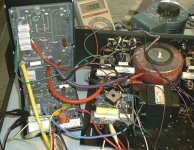
OK, I have the first amplifier up and running.
I still have some fine tuning to do, but initial listening tests have been quite positive. The biggest difference between it and the stock PS Audio model Two C plus is in the clarity and inner detailing. With the original amplifier you can, for example, hear the sound of a violin in a recording. With the new amplifier, you can actually hear the tone of the instrument, the sounds of the bow on the strings, and the resonance of the body. The difference is akin to what I'd expect from exchanging a cheap MM cartridge with a high quality MC unit. This is a much larger improvement than I had expected.
Another big improvement is with the bass and dynamics. I expected more authority with the new amplifier based on the higher power output, but the dynamics have completely taken me by surprise. Loud transients, like percussion, appear to almost jump out at you, and sound much more realistic. Even with casual listening this is very noticeable, and can be a bit scary if you're not expecting the sound of a live drummer in your listening room.
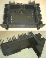
Other than that, the soundstage is a bit wider and better defined, with more space between instruments, and much more depth. As well, with the parallelled output devices and larger heatsinks, the amp runs very cool, unlike the original design.
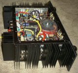
Overall, the new amplifier is a whole lot more musical and listenable. Swapping back to the original amplifier, it now sounds like a cartoon image instead of the real thing. The difference is simply amazing.
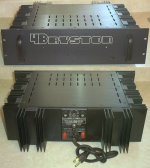
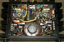
Anyways, here is a pic of the completed amplifier:
OK, I have the first amplifier up and running.
I still have some fine tuning to do, but initial listening tests have been quite positive. The biggest difference between it and the stock PS Audio model Two C plus is in the clarity and inner detailing. With the original amplifier you can, for example, hear the sound of a violin in a recording. With the new amplifier, you can actually hear the tone of the instrument, the sounds of the bow on the strings, and the resonance of the body. The difference is akin to what I'd expect from exchanging a cheap MM cartridge with a high quality MC unit. This is a much larger improvement than I had expected.
Another big improvement is with the bass and dynamics. I expected more authority with the new amplifier based on the higher power output, but the dynamics have completely taken me by surprise. Loud transients, like percussion, appear to almost jump out at you, and sound much more realistic. Even with casual listening this is very noticeable, and can be a bit scary if you're not expecting the sound of a live drummer in your listening room.
Other than that, the soundstage is a bit wider and better defined, with more space between instruments, and much more depth. As well, with the parallelled output devices and larger heatsinks, the amp runs very cool, unlike the original design.
Overall, the new amplifier is a whole lot more musical and listenable. Swapping back to the original amplifier, it now sounds like a cartoon image instead of the real thing. The difference is simply amazing.
Anyways, here is a pic of the completed amplifier:
Attachments
Doug,
I'm really taken to this design.
How did it sound with the TIP41/42 drivers?
What accounts for the huge improvement?
I might consider better output transistors with less beta droop such as
MJ21193/MJ21194.
For inputs: 2SC2240 and 2SA970 have lower noise, higher beta.
Do you have the PCB layout available?
Take care
Tom

How did it sound with the TIP41/42 drivers?
I never had a chance to compare them directly, I only used them with some output transistors that turned out to be counterfeit and unusable. When I replaced the outputs with new ON Semiconductor devices I replaced the drivers as well.
What accounts for the huge improvement?
Better quality parts, solder, and power supply improvements.
Do you have the PCB layout available?
I have it, but it would not be of much use unless the boards were to be installed in a 4B chassis. I would design a generic pcb much differently.
How can we be sure this is not the original Bryston parts? Sorry, i couldent resist, it looks so well made
Thank you for the compliment!
Actually, a real Bryston looks quite different than this on the inside!
Take care,
Doug
- Status
- This old topic is closed. If you want to reopen this topic, contact a moderator using the "Report Post" button.
- Home
- Amplifiers
- Solid State
- New Amplifier Project