Hello amp folks!
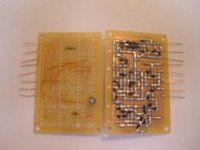
I have been working on a SS amp 'prototype' and finally get to where I can see some results. Most of the amp circuit is still laid out on a bread board, which may impede some high freq response, but that will be tested later. There are 4 of these boards, here are two, 1 per channel. Sometime in the somewhat near future, I will invest in some actual PCB's instead of this Radio Shack junk. I guess it works for now though...
BTW, this amp has an input Z nearly 100K and a low freq. rolloff around 14Hz. The feedback loop consists of a 2.2M resistor to the gate of -input transistor, and 27K in series with 1uF to GND, this gives a gain of around 80. Oddly when the gain is set lower, the amp isn't as fast and becomes more unstable.
Attachments
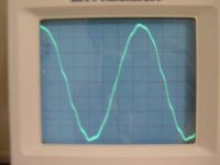
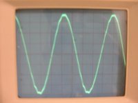
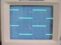
Your 200 and 300kHz shots show obvious signs of oscilation. Why are you using feedback resistors in the megaohm range? For FET input, bias current is non-existent, so you could just as well use nearly any practical value, as long as you kept it fairly low, so it does not make a filter with the (possibly substantial) input capacitance at too low a frequency, which only increases chances for instability!
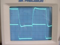
Ilimzn is right, the 1st 3 scope shots shows oscillation, the 50khz squarewave shows that these seem to be caused by slewing or anytime the error voltage is big enough.
You will need to finetune your feedback compensation, the most delicate work when designing an amp with gnfb.
As i mentioned already quite often, an amp not oscillating at idle does not mean that it is stable.
Mike
You will need to finetune your feedback compensation, the most delicate work when designing an amp with gnfb.
As i mentioned already quite often, an amp not oscillating at idle does not mean that it is stable.
Mike
Thanks for the replys guys. The values of nfb can be reduced, I only did this so that the DC blocking cap could be 1uF during testing. Obviously, this does not have to be so. They don't have to be that small because the input capacitance of the input FET's is around 3.5pF, but your right, 2.2M is too large. I'm sure this is reason for an occilation that is referenced to the input gain pot setting.
The occilation doesn't occur near as bad when the load resistor is removed. Of course an amp with no load is kinda worthless.
http://www.fairchildsemi.com/ds/KS/KSK595H.pdf
There is only 2 stages plus a darlington output in the nfb loop. The first is a cascoded j-fet diff, the second is a cascode BJT diff, biased by a Thompson mirror. Figuring out the compensation is certainly a task. There may be quite a bit of this being caused by the input filter/feedback. I will test this for any changes.
Thanks
Hi
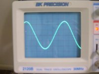
After some tweeking on the nfb loop impeadance and the compensation, there is some improvement. The breadboard probably affects the compensation scheme. I had to add a 10 Ohm resistor in series with 100nF to the output to make the amp stable with a speaker load, but it is stable on the 4 Ohm load resistor without the capacitor load, which seems more like typical amp behavior. However, this test was done across the 4 Ohm resistor || 10 Ohm + 100nF.
10 Vp @ 10KHz....
Attachments
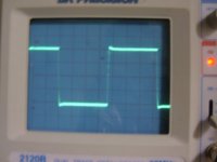
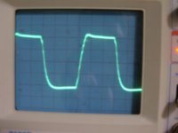
This photo had to be taken quickly because my 1/4W 10 Ohm resistor will burn up. This circuit already smoked one and kept on going with a 100KHz square wave, but as calculated after the fact, I guess it should have burned up. I measure around 800nS of time for the voltage to rise from -10 V to +10 V. I'm not an expert with the spec ratings of common amps, what would be a respectable slew rate for a 25W 4 Ohm amp?
Still have some tweeking to do.....
Anyway, 10 V @ 100KHz square wave, (well close to a square wave ) ...
I measure around 800nS of time for the voltage to rise from -10 V to +10 V. I'm not an expert with the spec ratings of common amps, what would be a respectable slew rate for a 25W 4 Ohm amp?Still have some tweeking to do.....
Anyway, 10 V @ 100KHz square wave, (well close to a square wave
) ...Attachments
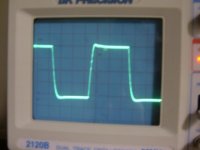
CBS240 said:Same test, 10 V @ 50KHz square wave...
those new scope images
shows extemely nice waves!
considering 10 Volt into 4 Ohm is a high sound output level
You can also test if is stable with capacitive load
For this test:
- You put 100nF film cap across that 4 Ohm
- And the test signal output should be very low: Like 100-200 mV RMS (0.1-0.2 V) at 1 kHz
Mr. Leach says in his Leach Amplifier website ( LOW TIM )
that one of the worst capacitive test is to put 2.2uF across 8 Ohm.
Translated to 4 Ohm, worst test would be: 4.7uF across 4 Ohm.
.... but try 100nF or so, first!
If you observe some signs of oscillation
The Cure is what we often see in SAFE power amplifiers outputs:
One 10 Ohm power resistor
with a some 8-10 turns wounded 1-2 mm wire as a coil around this resistor
And this inductance attached in parallel with resistor.
When you have tweaked a bit more, into further perfection
you may want to share this circuit with us ...
As I said, those latest two tests you posted are very good!
Regards
lineup
CBS240, be very careful of your load. You have to drive EVERY value cap., not just one value with a square wave. However, a 1KHz square wave will keep the peak current down and tell you what you need to know. A resistor load is not a real load. A resistor with a specific capacitor value is not a real load either. You must try a whole range of capacitors, up to 10 uF. Somewhere, there will be a worst case, maybe at .1uf, but often at .01 or 1 uf. You must try each range to be sure.
Hi
The test of 10V is just to show it is in fact stable to that voltage output with that current. I will test with different capacitor values across the 4 Ohm resistor with 1KHz and 10Khz. I can tell you the 100KHz wave form is slightly wavy(lack of very high freqs.) with the 100nF || 4 Ohms. Of course if I could hear 100KHz, I would never get any sleep.
Results later....
Thanx
well,
if the 100kHz is wacky, it should be so, more or less, in any load,
capacitive load test
are to be done in 500-2000 Hz area
with square wave
and very low power output
like I said a few 100 mV RMS ( surely below 1 V RMS )
if there is a capacitive load problem
it can shows as ringing and overshoting in those squarewaves
but I would guess your amp is not having this problem with CAP LOADS
because none of your posted square waves
shows any signs of too much overshooting or any ringing
Yes, but the compensation is kinda fragile, in that there are 2 miller feedback compensation caps for the second diff transistors, 3pF and 4pF. I can tell a large difference when changing either of the caps by + or - 1pF, but it is a stable difference. When I actually assemble this circuit on a PCB the scheme may change. There was some terrible instability with 10nF but not with 100nF before I made the latest adjustments, I will certainly be looking for this as well.
thanks for the info on what to test for, will see these results later.
Incidently, there seems to be some occilation which may be due to my scope and crappy grounding scheme. It is larger on the input than the output , about 40MHz. I think assembling on the PCB may fix this.
thanks for the info on what to test for, will see these results later.
Incidently, there seems to be some occilation which may be due to my scope and crappy grounding scheme. It is larger on the input than the output
, about 40MHz. I think assembling on the PCB may fix this.Hi
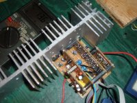
How many individual transistors can YOU cram into a 3 X 5 in board? As for me, 127.
The 40Mhz occilation is gone now that the board is assembled, the 60Hz buzz is gone as well now that I rewired the grounding scheme.
The DC offset is 15-20mV, with a Av of 65. As always(it seems) it is a work in progress, but is completely home-made, true DIYaudio. The op-amp on the bottom board is a duel op-amp but used only as control for the voltage regulator cirucits(two smaller boards) as a switch so the amp will turn on or off with a logic +5V. Everything else is discrete. Each side is a mirror of the other. Still not completed, I need to come up with an enclosure. And build the other two channels....
How many individual transistors can YOU cram into a 3 X 5 in board? As for me, 127.
The 40Mhz occilation is gone now that the board is assembled, the 60Hz buzz is gone as well now that I rewired the grounding scheme.
The DC offset is 15-20mV, with a Av of 65. As always(it seems) it is a work in progress, but is completely home-made, true DIYaudio.
The op-amp on the bottom board is a duel op-amp but used only as control for the voltage regulator cirucits(two smaller boards) as a switch so the amp will turn on or off with a logic +5V. Everything else is discrete. Each side is a mirror of the other. Still not completed, I need to come up with an enclosure. And build the other two channels....Attachments
CBS240 said:This photo had to be taken quickly because my 1/4W 10 Ohm resistor will burn up. This circuit already smoked one and kept on going with a 100KHz square wave, but as calculated after the fact, I guess it should have burned up.
Still have some tweeking to do.....
Anyway, 10 V @ 100KHz square wave, (well close to a square wave
Looks like in a positive half it is still not stable.
Hi,
There are certain transistors that must be matched in this circuit or it will not function. Well, it may function but the compensation required to stabilize it will destroy the BW. I noticed that if I placed the soldering iron on top of one transistor in the mirror there becomes overshoot on the square wave, and as it cools, the overshoot dissipates proportional to the heat difference. Overall stability is a little better since building on a PCB.
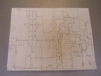
The circuit below is a sketch of the amp section. I have 10 V on each rail to sacrifice before driving the outputs, so rail to rail operation is possible. With a few resistor changes, I’m sure this circuit could be modified for a source follower mosfet output. All resistors except the ones numbered are SMD. The bias in the first diff is dependent on the collector voltage of the second diff CCS. The bias reference is the 6mA bias from the second CCS. No DC offset pot is needed. The current demand of the circuit(not counting output stage) is about 10mA at idle, but it is not symmetrical with audio because of the extra dependent current source. The voltage regulator circuits that supply the +/-28 V is actually 2 complementary small discrete amps with a DC reference to a Zener voltage divider with a relatively large cap. That circuit amplifies the ripple from the voltage doubling circuit to cancel it out and also drive the ‘dynamic impedance’ of the amp thus having better load rejection than just a simple series Zener regulator. After all, what we listen too is actually the power supply, modulated with an audio signal.
The input bias seems low, but is moderate for that particular transistor with around 5V Vds. I don’t know if these transistors are intended for this purpose, but they certainly work quite well. The gain of the second stage is very high. As always, an ongoing project…
Hope the picture is legible
There are certain transistors that must be matched in this circuit or it will not function. Well, it may function but the compensation required to stabilize it will destroy the BW. I noticed that if I placed the soldering iron on top of one transistor in the mirror there becomes overshoot on the square wave, and as it cools, the overshoot dissipates proportional to the heat difference. Overall stability is a little better since building on a PCB.
The circuit below is a sketch of the amp section. I have 10 V on each rail to sacrifice before driving the outputs, so rail to rail operation is possible. With a few resistor changes, I’m sure this circuit could be modified for a source follower mosfet output. All resistors except the ones numbered are SMD. The bias in the first diff is dependent on the collector voltage of the second diff CCS.
The bias reference is the 6mA bias from the second CCS. No DC offset pot is needed. The current demand of the circuit(not counting output stage) is about 10mA at idle, but it is not symmetrical with audio because of the extra dependent current source. The voltage regulator circuits that supply the +/-28 V is actually 2 complementary small discrete amps with a DC reference to a Zener voltage divider with a relatively large cap. That circuit amplifies the ripple from the voltage doubling circuit to cancel it out and also drive the ‘dynamic impedance’ of the amp thus having better load rejection than just a simple series Zener regulator. After all, what we listen too is actually the power supply, modulated with an audio signal. The input bias seems low, but is moderate for that particular transistor with around 5V Vds. I don’t know if these transistors are intended for this purpose, but they certainly work quite well. The gain of the second stage is very high. As always, an ongoing project…
Hope the picture is legible
Attachments
- Status
- This old topic is closed. If you want to reopen this topic, contact a moderator using the "Report Post" button.
- Home
- Amplifiers
- Solid State
- New amp results