BobEllis
Understood, so the only reason most folk have reported less heat is that they play music. Please permit me to rephrase your eloquent post earlier in this thread:
The current source FETs carry the full current bias indicated on the spreadsheet 100% of the time but share the voltage swing with the gain FETs so that the voltage across them reduces proportionally to the signal amplitude.
The gain FET's share the current load with the speakers and swing their voltage with the signal input 100% of the time so that they burden the entire current bias only when there is no current to the speaker. Is this an acceptable explanation? If it is, then let's move on.
The AC current gain on the spreadsheet indicates a 50% default entry that claims the current source FETs carry "half the current" at this value. Does this mean half the current indicated in the total amp bias number of the cell directly above it in the spreadsheet or some other number which is not represented? If it is indeed the number above it (ie: the "total bias for one channel being one monoblock"), then a 50% AC current gain implies that a 4A entry on that line will result in each of 4 devices carrying only one amp (ie: the two gain FETs carrying half the amount and the two current source FETs carrying the remaining 2A. If this is not so, then please explain why it isn't. I am assuming this AC current gain is used to more closely match the speaker load to the bias available so that raising it will starve the gain FETs on signals which are located on a speakers impedence dip, am I correct? If so then why does the spreadsheet state that raising this value will provide greater current peaks?
It had been suggested earlier that these concepts may be beyond my ken and that I should perhaps consult some books on Ohm's Law and perhaps learn the meaning of P=VI so please forgive me in advance for any naivete which I have exhibited in my questions")
Understood, so the only reason most folk have reported less heat is that they play music. Please permit me to rephrase your eloquent post earlier in this thread:
The current source FETs carry the full current bias indicated on the spreadsheet 100% of the time but share the voltage swing with the gain FETs so that the voltage across them reduces proportionally to the signal amplitude.
The gain FET's share the current load with the speakers and swing their voltage with the signal input 100% of the time so that they burden the entire current bias only when there is no current to the speaker. Is this an acceptable explanation? If it is, then let's move on.
The AC current gain on the spreadsheet indicates a 50% default entry that claims the current source FETs carry "half the current" at this value. Does this mean half the current indicated in the total amp bias number of the cell directly above it in the spreadsheet or some other number which is not represented? If it is indeed the number above it (ie: the "total bias for one channel being one monoblock"), then a 50% AC current gain implies that a 4A entry on that line will result in each of 4 devices carrying only one amp (ie: the two gain FETs carrying half the amount and the two current source FETs carrying the remaining 2A. If this is not so, then please explain why it isn't. I am assuming this AC current gain is used to more closely match the speaker load to the bias available so that raising it will starve the gain FETs on signals which are located on a speakers impedence dip, am I correct? If so then why does the spreadsheet state that raising this value will provide greater current peaks?
It had been suggested earlier that these concepts may be beyond my ken and that I should perhaps consult some books on Ohm's Law and perhaps learn the meaning of P=VI so please forgive me in advance for any naivete which I have exhibited in my questions
wuffwaff
If I remember correctly, I looked at an alternate spreadsheet by another member that also had its errata but it seemed to more accurately represent the current bias/speaker load relationship than yours. Your findings indicate that you are suggesting too much bias for a given speaker impedence. I'm glad you actually tested it and saw this for yourself.
If I remember correctly, I looked at an alternate spreadsheet by another member that also had its errata but it seemed to more accurately represent the current bias/speaker load relationship than yours. Your findings indicate that you are suggesting too much bias for a given speaker impedence. I'm glad you actually tested it and saw this for yourself.
Darn, i was hoping osmeone else would take a stab at explaining AC Current gain.  At least you have the heat load portion under control.
In very simplistic terms (about the depth of my understanding of this topic) The AC current gain of the aleph circuit functions as a dynamic bias adjustment, to ensure that the current source does not shut off. The capacitor in the circuit ensures that only the AC portion of the signal is fed back into the constant current source, hence the term AC current gain. Eliminate the capacitor and you'll have current gain at DC output.
The way I understand it, 50% current gain means that the bias is half of the total peak output. Each side's current sources take half the total bias, which would limit the maximum output current to half of the total bias without the aleph current source. (use 100 amps total bias to see more significant digits)
I have not played with it, but varying the AC current gain is supposed to change the amp's sound. More gain means punchier bass, less gain means sweeter highs.
the AC current gain really has nothing to do with "matching bias to the speaker load" except that as we all should know real world speakers do not present a constant load. "Excess" current capability at 8 ohms is what allows the amp to drive a speaker with an impedance dropping to four ohms without running out of steam.
If I understand what wuffwaff was saying, his measurements were a response to my earlier statement that you probably wouldn't swing to within 2 volts of the rails. I don't quite understand how that bootstrap capacitor lets you drive a voltage higher than the rails, but it works. What he was showing was that as current increases (load impedance drops) he gets more losses in the current source and output resistors. this results in reduced voltage swing available.
He had plenty of bias to meet the load current requirement. With lower bias or AC current gain he would have seen something like 2 V at 8 ohms, 4 v at 4 ohms and 12 volts at 2 ohms.
Just because you have more current available than the minimum to supply your load at the stated outpur voltage doesn't mean it's wrong. The aleph series generall sounds better the higher it is biased.
the self study suggestions wouldn't hurt if you really seek an in depth understanding.
At least you have the heat load portion under control.In very simplistic terms (about the depth of my understanding of this topic) The AC current gain of the aleph circuit functions as a dynamic bias adjustment, to ensure that the current source does not shut off. The capacitor in the circuit ensures that only the AC portion of the signal is fed back into the constant current source, hence the term AC current gain. Eliminate the capacitor and you'll have current gain at DC output.
The way I understand it, 50% current gain means that the bias is half of the total peak output. Each side's current sources take half the total bias, which would limit the maximum output current to half of the total bias without the aleph current source. (use 100 amps total bias to see more significant digits)
I have not played with it, but varying the AC current gain is supposed to change the amp's sound. More gain means punchier bass, less gain means sweeter highs.
the AC current gain really has nothing to do with "matching bias to the speaker load" except that as we all should know real world speakers do not present a constant load. "Excess" current capability at 8 ohms is what allows the amp to drive a speaker with an impedance dropping to four ohms without running out of steam.
If I understand what wuffwaff was saying, his measurements were a response to my earlier statement that you probably wouldn't swing to within 2 volts of the rails. I don't quite understand how that bootstrap capacitor lets you drive a voltage higher than the rails, but it works. What he was showing was that as current increases (load impedance drops) he gets more losses in the current source and output resistors. this results in reduced voltage swing available.
He had plenty of bias to meet the load current requirement. With lower bias or AC current gain he would have seen something like 2 V at 8 ohms, 4 v at 4 ohms and 12 volts at 2 ohms.
Just because you have more current available than the minimum to supply your load at the stated outpur voltage doesn't mean it's wrong. The aleph series generall sounds better the higher it is biased.
the self study suggestions wouldn't hurt if you really seek an in depth understanding.
Hi Bob,
"I don't quite understand how that bootstrap capacitor lets you drive a voltage higher than the rails, but it works."
Look at the bootstrap caps (C3 and C5). They are not connected to ground but to the output. So if there´s say 10V over them and the output rises near the supply voltage the voltage at the positive side of the cap will be over the supply voltage. This way you can drive the gate of Q1/Q10 with a voltage higher than the supply voltage.
William
For anyone following this thread, wuffwaff has quietly introduced an updated calculator here in this thread. It's nice to see that he is responsive to the concerns of the membership here.
Youdou,
let´s say that all the activity in this thread has motivated me to make some changes asked for by people who mailed me and wanted some more information or a digit or two more in the results. I also put in a few new things to give some extra information.
The nice thing is that the new version won´t give you different results in any important area (changes are pointed out in the other thread)
William
Aleph X / Aleph 2 discrepancy
Hey everyone,
This may have been asked before, but I can't seem to find the answer anywhere, so here it is:
If the Aleph X shares the same output section as the other Aleph amplifiers (e.g. Aleph 2 or 5) then why does the power output drop into lower impedance loads with the Aleph X, while the spec sheets for the Aleph 2 and 5 clearly indicate an increase in power into lower impedance loads. One of these two must be incorrect, so is Nelson lying about the output capabilities of his amplifiers (doubtful), or is the spreadsheet incorrect? If it’s neither of those things, then where does the difference lie between these two amplifiers?
I’m just trying to correlate the 3 amp bias and 45 volt rails of the Aleph 2 with something on the spreadsheet, but it’s telling me the Aleph 2 will only put out 36 watts under those conditions. How can you accurately calculate the output power for a normal Aleph if it's different than the Aleph X?
If someone could explain this to me, I’d really appreciate it!
Cheers,
Owen C.
yes, the AX shares its output section topology with the Aleph series. There are two of them, so the total bias is split between the output sections. If you give them enough bias, the output will double as the load impedance goes from 8 ohms to 4 ohms and double again going to 2 ohms. Just don't ask me for heat sink money
BTW, you forgot to factor in AC current gain in your Aleph 2 calculation - if it is 50% then your peak current will be 6 amps at 3 amps bias. Does that make you feel better about Nelson?
BTW, you forgot to factor in AC current gain in your Aleph 2 calculation - if it is 50% then your peak current will be 6 amps at 3 amps bias. Does that make you feel better about Nelson?
Hello Owen,
you can´t really use the Ax sheet for a normal Aleph. You need to half the supply voltage and double the bias to get results that are (nearly) correct. It is better to use the Aleph sheet that should also be around somewhere on the forum.
Think of published specs as a marketing tool....like fuel consumption figures for cars
William
Using the Aleph-Power sheet, I can only get the Aleph 2 to reconcile with the service manual by setting the AC current gain to 67%.
Settings were 3.0amp/channel bias, 45V rails. Dissipation was listed at 270W.
At 50% AC current gain it gave 110W RMS into 8 ohm, 72W RMS into 4.
At 67% AC current gain it gave 110W RMS into 8 ohm, 165W into 4 ohm. Closer to the 160W RMS @ 4 ohm claimed in the service manual.
Is there a newer sheet, an error on my side, as expected, or something screwy?
Ok. For some reason I had the idea that the Aleph 2 was at 50% AC current gain was all.
Veryifying stock cars acceleration times is a great way to get holiday greeting cards from all your friends at the transmission shop. Here in America its the 1/4 mile (402 meters) that counts the most. Maybe wed care about turns more if we could take our cars to the Hockenheim Ring.
Veryifying stock cars acceleration times is a great way to get holiday greeting cards from all your friends at the transmission shop. Here in America its the 1/4 mile (402 meters) that counts the most. Maybe wed care about turns more if we could take our cars to the Hockenheim Ring.
Let's put an end to this...
Hey guys,
I posted a question similar to the one tweeker is asking here. If you read back a few posts, you'll find it pretty quickly. I was having a hard time correlating the power output predictions of the Aleph spreadsheet, and the published specs from the Aleph 2 service manual.
Wuffwaff,
You gave me a similar answer to the one you're giving tweeker now (Basically accusing Nelson of exaggerating his power specs) , and after doing some measurements I can confirm that it's definitely the spreadsheet that is in error, not the published specs of the Aleph 2.
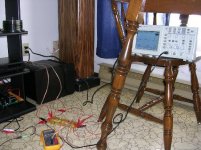
I used my completely stock Aleph 2 amplifier (built exactly as per the service manual schematic) for testing two dummy loads of exactly 9.5 ohms and 4.8 ohms. Using a 1000Hz sine wave input, and with the dummy loads connected to the ouput, I took current and voltage measurements using my Fluke meter and a Tektronix digital scope.
The Aleph 2 managed 4.18A pk into the 9.5 ohm load, which works out to 82.98 watts without any clipping visible on the scope. With the 4.8 ohm load, the Aleph 2 managed 7.63A pk, which gives you about 139.67 watts without any sign of clipping.
Now, what's worth noting is that my preamp was at full volume, and I'm pretty sure I could have managed a higher output if I had a little more drive from the function generator (my laptop). With the given setup, I couldn't even gets the amplifiers to clip.
So, tweeker, there you have it. The Aleph 2 does seem to accomplish its published 0-100km/h rating without a fuss. I think the spreadsheet might be fun to play around with, but it obviously falls short of describing the actual operating conditions of the Aleph, at least when it comes to power output.
I'll include a picture of the test setup, just so you know I'm not making this stuff up.
Hope this helps things,
Cheers,
Owen C.
Hey guys,
I posted a question similar to the one tweeker is asking here. If you read back a few posts, you'll find it pretty quickly. I was having a hard time correlating the power output predictions of the Aleph spreadsheet, and the published specs from the Aleph 2 service manual.
Wuffwaff,
You gave me a similar answer to the one you're giving tweeker now (Basically accusing Nelson of exaggerating his power specs) , and after doing some measurements I can confirm that it's definitely the spreadsheet that is in error, not the published specs of the Aleph 2.
I used my completely stock Aleph 2 amplifier (built exactly as per the service manual schematic) for testing two dummy loads of exactly 9.5 ohms and 4.8 ohms. Using a 1000Hz sine wave input, and with the dummy loads connected to the ouput, I took current and voltage measurements using my Fluke meter and a Tektronix digital scope.
The Aleph 2 managed 4.18A pk into the 9.5 ohm load, which works out to 82.98 watts without any clipping visible on the scope. With the 4.8 ohm load, the Aleph 2 managed 7.63A pk, which gives you about 139.67 watts without any sign of clipping.
Now, what's worth noting is that my preamp was at full volume, and I'm pretty sure I could have managed a higher output if I had a little more drive from the function generator (my laptop). With the given setup, I couldn't even gets the amplifiers to clip.
So, tweeker, there you have it. The Aleph 2 does seem to accomplish its published 0-100km/h rating without a fuss. I think the spreadsheet might be fun to play around with, but it obviously falls short of describing the actual operating conditions of the Aleph, at least when it comes to power output.
I'll include a picture of the test setup, just so you know I'm not making this stuff up.
Hope this helps things,
Cheers,
Owen C.
Attachments
Don't get me wrong... I'm not calling the sheet useless, I'm just saying that there are one too many variables to get an accurate look at what the power output would actually be.
Either you have to assume a given output power to get the AC current gain, or you have to assume an AC current gain to get a specific output power. Either way, unless you're sure about one or the other, it's the equivalent of having a "make the answer whatever you want it to be" entry on the spreadsheet.
The sheet is great for getting an idea of what's going on, and for power dissipation and the like, but it does seem a bit questionable when it comes to true power output.
Anyways, just my two cents.
Cheers,
Owen C.
- Status
- This old topic is closed. If you want to reopen this topic, contact a moderator using the "Report Post" button.
- Home
- Amplifiers
- Pass Labs
- NEW Aleph-X calculation sheet: AXE-1