Banned
Joined 2002
fcel said:I'm patiently waiting for my parts from Jason. Chassis is all ready to go.
I'm sorry i can't send your parts till you show us pics of the chassis

OK all the kits are done.. I went out and bought another static strap because i lost mine in my last move.. ALL i have to do now is seperate the Output fet's and then start shipping.. Those who bought psu kits will have to send me $$ for shipping..
J
I finished mine a while backI'm sorry i can't send your parts till you show us pics of the chassis
An externally hosted image should be here but it was not working when we last tested it.
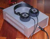
It's empty and awaiting the parts
Thanks!
Yes, I would definitely like to change the front plate with a thicker one some time, the same goas to the bottom plate as that one also is only 2mm. It is just that I had really easy access to these plates. I do not really mind the screws, but it would be nice if they could at least sink into the aluminum a bit.
Yes, I would definitely like to change the front plate with a thicker one some time, the same goas to the bottom plate as that one also is only 2mm. It is just that I had really easy access to these plates. I do not really mind the screws, but it would be nice if they could at least sink into the aluminum a bit.
jleaman said:
ALL i have to do now is seperate the Output fet's and then start shipping.. Those who bought psu kits will have to send me $$ for shipping..
J
How much for each kit to California and when?
- Phil
Banned
Joined 2002
Phil K said:
How much for each kit to California and when?
- Phil
You got,
( Philip Klein 1 x A30 2 Pus Shipping Not paid yet. )
Your box will not cost much.. The only one i can see being lots is ( Tweeker's )
He bought 4 psu and 6 A30's WOAH..
I need to get mine started soon..
Banned
Joined 2002
Banned
Joined 2002
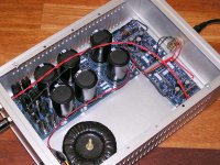
Interior view. You can't quite see it from this pic, but there is 0.2F in the powersupply in a CRC configuration. I also used Ultrafast Soft Recovery diodes from International Rectifier for the rectifier bridge. Major overkill for a headphone amp, but this supply is deadly quiet even without using a regulation stage. I left room in the chassis to add separate regulators for each channel in the future if I change my mind. I designed for +/-15V rails, but ended up with /-17V. Gotta luv Plitron trafos.
Attachments
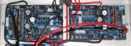
Closer view of the stuffed amplifier pcbs's. Nothing exotic used here. Matched the IR9610's to less than 0.1mV, and ended up with +8mV and -11mV DC offsets for the left and right channels respectively, probably due to resistor mismatches. The bias is set at 0.25A and the CCS at 50%. Max power into the Grado's is 3W.
How does it sound? Was real bright at first listen but after 10-15 hours of burn in time, the sound came right back to neutral. The sound is very dynamic, and I have never heard such deep and well controlled bass in my life. Crisp and clear but not etched or fatiguing. Amazing reproduction of vocals, very natural.
Oh yeah, I almost forgot to point out that the output transistors are not missing, but are underneath the pcb's and mounted to the chassis for heatsinking. Used IRF610's for the outputs.
Attachments
Great job, Metalman Now lets see, in order to scale this thing for a headphone amp: Supply rails +/- 15V, output devices irf610,
source resistors 1 ohm, output resistor 0,47 ohm. Smaller trafo. Thats what I gathered from your posts and pics. Is there any other changes needed?
Steen.
Now lets see, in order to scale this thing for a headphone amp: Supply rails +/- 15V, output devices irf610, source resistors 1 ohm, output resistor 0,47 ohm. Smaller trafo. Thats what I gathered from your posts and pics. Is there any other changes needed?
Steen.
metalman said:Interior view. You can't quite see it from this pic, but there is 0.2F in the powersupply in a CRC configuration. I also used Ultrafast Soft Recovery diodes from International Rectifier for the rectifier bridge. Major overkill for a headphone amp, but this supply is deadly quiet even without using a regulation stage. I left room in the chassis to add separate regulators for each channel in the future if I change my mind. I designed for +/-15V rails, but ended up with /-17V. Gotta luv Plitron trafos.
Hey there Tin Man, those caps look good.
What value are those power resistors in the PSU?
Regards
Anthony
A few of the resistor values need to be adjusted, but not many. I'll put together a complete schematic for you and post it.Originally posted by steenoe
Is there any other changes needed?
3 x 27 ohm on each rail. Quite high in comparison with what you would use on power amplifiers, but as this is only dealing with 0.5A total current, I could really ramp it up to drop the ripple, which measures at 0.5 mV(peak to peak).Originally posted by Coulomb
What value are those power resistors in the PSU?
Cheers, Terry
metalman said:
A few of the resistor values need to be adjusted, but not many. I'll put together a complete schematic for you and post it.
3 x 27 ohm on each rail. Quite high in comparison with what you would use on power amplifiers, but as this is only dealing with 0.5A total current, I could really ramp it up to drop the ripple, which measures at 0.5 mV(peak to peak).
Cheers, Terry
Thanks Terry, I tried 5 x 50R all the way down to 2 x 50R on my Mini A's and the rail VD was half the Supply voltage. I figure that when using one PSU with two Mini A's 5 x 500R is going to be required to suppress ripple without crushing the rail voltage.
Regards
Anthony
I could use a little direction in choosing some PCB screw terminals. That's to obviate problems with my ready-fire-aim chassis design process.
I would like to know the general consensus of the group on Phoenix, On-Shore & 3M. What do you like?
I am specifically looking to terminate
AC0/AC0, AC1/AC1 (8mm pitch?)
-V, Gnd, & +V (5mm?) on the PS boards.
I am additionally looking for the 3 position PCB 90 terminal for
Out/Gnd.CGnd (5mm?)
2 position SG/UN
I would just like to avoid ordering the wrong terminals three times. Digikey has about 5000 choices.
- Status
- This old topic is closed. If you want to reopen this topic, contact a moderator using the "Report Post" button.
- Home
- Amplifiers
- Pass Labs
- New Aleph Mini PCB GB