fcel said:Another question .... what are the values of those resistors located between the capacitors? Your Power Supply Parts List shows it as a short circuit jumper for R3 to R12. Is that something we should calculate on our own? Thanks.
You are correct. If you were to follow the Pass Labs schematic, there would just be a short circuit jumper there.
As for the CRC values, you will need to do some experimentation here. A value of a 0-2 ohms should work here (estimation). I am going to try a low value for my first amp, paralleling 5 - 3ohm 3w resistors per rail. With 5 of them, I will only get an R value of 3/5 an ohm, but I can always increase this later.
To calculate the voltage drop, take account for the current in the circuit. For the Mini-A, the current was 1A per channel, so the stereo power supply board would have 2A of current. Using a 3/5 ohm resistor on the voltage rail will cause a voltage drop of 1.2v (V = I * R). The 5 - 3W resistors will be equivalent to a single 15w resistor, so the resistors should be able to handle the power drop. (P = I^2 * R)
--
Brian
dhole said:I am having problems here. I think I have blown something up. i have a toroidal with 2x28v . I have stuffed the board but had some problems. if I only use one which connections (AC0 or AC1) do I use ? Why are there there these two sets ?
regards
dave
Hello mate, there are four pads for the AC in, as this PSU does both +/- rails you would need a CT or dual secondary transformer. The two inside Pads are common and form the GND rail, the two outside Pads are for the two primary connections.
The primary connections can be done in two ways, they can be the two ends of a single CT transformer or the two free ends of a dual secondary with the centre taps brigded. The bridged or CT leads from a transformer go to the two center pads. Take a look at the attached image, perhaps it will help explain Transformer secondaries.
Regards
Anthony
Attachments
OK Ok I understand ( a moment of foolishness )
I connected the AC up the wrong way.... doh nearly set the room on fire again... hehe
now I have two rails at 37.7 v
I presume this will drop when everything is running....
I cant get another 28-28 so I might get two 30-30 output toroidals ( they are the closest I can get in the uk as standard from farnell rapid etc. ) I should be able to use them I guess ?
dave
Coulomb said:
Hello mate, there are four pads for the AC in, as this PSU does both +/- rails you would need a CT or dual secondary transformer. The two inside Pads are common and form the GND rail, the two outside Pads are for the two primary connections.
The primary connections can be done in two ways, they can be the two ends of a single CT transformer or the two free ends of a dual secondary with the centre taps brigded. The bridged or CT leads from a transformer go to the two center pads. Take a look at the attached image, perhaps it will help explain Transformer secondaries.
Regards
Anthony
Here is an example of the Dual comlpimentary design that Brian's PSU uses.
Anthony
Attachments
dhole said:OK Ok I understand ( a moment of foolishness )
I connected the AC up the wrong way.... doh nearly set the room on fire again... hehe
now I have two rails at 37.7 v
I presume this will drop when everything is running....
I cant get another 28-28 so I might get two 30-30 output toroidals ( they are the closest I can get in the uk as standard from farnell rapid etc. ) I should be able to use them I guess ?
dave
Hello Dave, if you load the PSU with the resistors or Inductors, CRC or CLC, that will drop the rails.
Anthony
Raj1 said:Hi Brian,
Do you have an eta for my boards and parts for the mini a? I only ask as some of the other UK members already have their boards........
Sorry if I'm being a little premature......
Thnaks
Raja
Raja,
Your order shipped out just over a week ago when the big batch of international orders shipped out. I would expect it to arrive very soon.
--
Brian
dhole said:( a moment of foolishness )
I connected the AC up the wrong way.... doh nearly set the room on fire again... hehe
120 vac in the US is leathal(barely but still so), 220 vac in the UK is VERY leathal.
Word of caution to newbies..... If you have any questions just ASK. We are all here to help.
rabstg said:
120 vac in the US is leathal(barely but still so), 220 vac in the UK is VERY leathal.
Word of caution to newbies..... If you have any questions just ASK. We are all here to help.
I guess you do not subsrcibe to a Darwinian philosophy?
")
Anthony
Not much feedback on whether anyone is interested in some serious Caps for Brians PSU Boards.
Here is what I have narrowed the choices down too.
Panasonic- immediate availablility of 200 plus units
39,0000uF @50VDC 85Deg. 40x80 $13 each CAD plus shipping.
Cornell Dubillier - 90 Days Deliver Custom Order
39,000uF @50VDC 85Deg. 40x80 $18 each CAD plus shipping
To go ahead I would need orders for at least 200 peices, at 6 per kit that would be enough for 33 kits.
I myself would prefer the Panasonic Caps, even though the CDE are arguably a better cap, the convenience of the local supplier is a big plus. As this purposed GB would be run from Canada all Canadian taxes have been included in the price and would be applicable wherever they would be shipped to... Sorry..
In CAD dollars the savings for 6 Caps would be $51.12, Shipping would be extra whether through a GB or direct from Vendor.
If there is enough interest, I could ask Brian to help with an order page.
Regards
Anthony
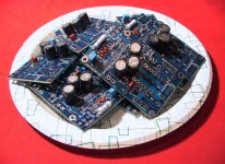
I finally started soldering my amp boards last night, soldering on all of the resistors for the static configuration (the resistors that don't change depending on the expected power output), the caps and diodes. My plan is to next match the IRF9610 devices and build a Mini-A with the first pair of boards. (stuffed 10 boards, as I ordered enough parts to stuff 10 boards)
Note the polarity of C1. The footprint on the pcb is incorrect for this component, and the cap should be mounted opposite the markings on the board.
Full size image:
http://diyamps.com/aleph/images/aleph-boards-big.jpg
--
Brian
Note the polarity of C1. The footprint on the pcb is incorrect for this component, and the cap should be mounted opposite the markings on the board.
Full size image:
http://diyamps.com/aleph/images/aleph-boards-big.jpg
--
Brian
Attachments
BrianGT said:I finally started soldering my amp boards last night, soldering on all of the resistors for the static configuration (the resistors that don't change depending on the expected power output), the caps and diodes. My plan is to next match the IRF9610 devices and build a Mini-A with the first pair of boards. (stuffed 10 boards, as I ordered enough parts to stuff 10 boards)
Note the polarity of C1. The footprint on the pcb is incorrect for this component, and the cap should be mounted opposite the markings on the board.
Full size image:
http://diyamps.com/aleph/images/aleph-boards-big.jpg
--
Brian
Is that one of them new fangled AntiStatic Paper plates?
Anthony
Coulomb said:
Is that one of them new fangled AntiStatic Paper plates?
Anthony
The only static sensitive component on the boards are the diodes, which should be just fine. I will mount the transistors on the boards at the time I am ready for testing.--
Brian
BrianGT said:
--
Brian
What time would that be? Dinner time?
Regards
Anthony
- Status
- This old topic is closed. If you want to reopen this topic, contact a moderator using the "Report Post" button.
- Home
- Amplifiers
- Pass Labs
- New Aleph Mini PCB GB