Yes, but fully balanced topology should not be chosen simply to remove the grounding issues when you know that you can still solve the problem
Well that isn't something that I know, I'm quite a novice at this 'design by listening' approach - when I worked professionally as an EE, I was a design- by-feeling-and-measurement guy. In those days, I didn't trust my own ears, but these days I do.
When I said "tweaking", it means plug and play and LISTEN. It takes tedious effort yes, but sometimes the result is surprising. For example, how can you say that Amp A is better than Amp B when you don't put each amp in their best implementation state?
How would I know what that 'best implementation state' was? By measurement, or by listening?
Often, by only changing the diode brand, the sound is surprisingly improved. I have tested/compared many diodes, I have tested many current sources.
But I'm not in doubt that changing components changes the sound. I want to do this in some methodical way, I need a heuristic to guide me here. Otherwise progress will be way too slow.
If you ask me why a cap can sound better than the other, especially in power supply, I think it is related with ESR.
Well then I suspect that I can use cheaper low ESR caps instead of those famous brands. I'm an optimiser by nature, I always seek the best bang-for-the-buck. Otherwise its no fun - doing a 'cost no object design' would result in too few customers.
I don't know electronics, but I indeed pay extreme attention to components specs and it's correlation to the resulting sound that I experience, so I can expect/predict that "this transistor will sound better here than that transistor".
Give some examples - what transistor specs do you pay attention to that relate to sound quality?
Caps in power supply are important. Bigger capacitance usually give worse sound, so to have enough capacitance I prefer to parallel smaller caps. That's already a widely accepted implementation practice.
But how low do you go? Is 100 * 100uF always going to surpass 1 * 10,000uF irrespective of the brands of each?
Again, I have many caps and I believe I have good ears. It is just a matter of time and willingness to compare them all. Unfortunately, this kind of tweaking can be considered "stupid" if you have proper electronics skill and knowledge.
Again, you presumably don't try randomly as there are simply too many combinations. So what guides you?
That's why I'm pessimistic that those clever experts have enough chance to develop good ears to build a better sounding amp.
Shouldn't that be 'optimistic' if you have the skill and they don't? Surely you don't want more competition with your own designs do you?
This is true when you notice in the old time some designers still use 78/79XX regulators. They didn't know like I did, that if they throw away those regulators they will have much better sounding gear.
I still have some in the designs I'm tweaking. What should I replace them with, and why? They're already sounding pretty good to me, what kinds of improvements might I attain by substituting them?
I still have some in the designs I'm tweaking. What should I replace them with, and why? They're already sounding pretty good to me, what kinds of improvements might I attain by substituting them?[/QUOTE]
Hi.Nazar BL have some power supply suggestions.They have bc546/556 and only mkp capacitors at the output.He says he gets very good results with them.He calls it "electronic capacitor"
Hi.Nazar BL have some power supply suggestions.They have bc546/556 and only mkp capacitors at the output.He says he gets very good results with them.He calls it "electronic capacitor"

Thank you mods ")
Prof smith - see first post for link.
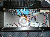
Now a question: Is this xmfr too close to the pcb & should I mount it on the right hand side which is where the speaker outs & PS in are?
The first pic shows the Naksa mounted, On the back panel, the RCA inputs are on the left of the pic; the speakers out & PS-in are on the right. On the front panel the grey wires are the in & out to the two pots left & right. The wires tied in a knot are for front panel leds which I will attach for left 7 right channel.
Prof smith - see first post for link.
Now a question: Is this xmfr too close to the pcb & should I mount it on the right hand side which is where the speaker outs & PS in are?
The first pic shows the Naksa mounted, On the back panel, the RCA inputs are on the left of the pic; the speakers out & PS-in are on the right. On the front panel the grey wires are the in & out to the two pots left & right. The wires tied in a knot are for front panel leds which I will attach for left 7 right channel.
Attachments
Now a question: Is this xmfr too close to the pcb & should I mount it on the right hand side which is where the speaker outs & PS in are?
From my experience, transformer induction is audible but I have never gone extreme in the implementation. Many have used grounded copper sheet/plate to shield the transformer. I used steel plate in my latest amp project.
Transformer orientation seems already okay. Position is of course better on the right because it is farther to the line level input on the left. But I prefer physical balance (transformer in the center). Attention to detail, when required, can be done with the shielding.
where can more information on this NAKSA be found?
Hello
If you want to buy another amp, this time you should buy a ready made one with all things and power supply allready connected in a case.
Bye
Gaetan
Hello
If you want to buy another amp, this time you should buy a ready made one with all things and power supply allready connected in a case.
Bye
Gaetan
hi,
I agree and I also think that if a new amp comes along and is claimed to be far better than the one it supercedes (as with this particular one) one or the other is flawed. This is called law of diminishing returns.
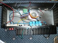
Just about finished - everything done except the leds to be connected ( these are the wires hanging over the front - there are 3 wires for two leds on each side - I'll only be connecting one led each side.)
This turned out to be a really neat fit for the Naksa board. I will look at an LDR lightspeed vol. control & also maybe re-doing the front panel into something more suited to the hopefully high quality sound of this amp - if it sounds special, I want to make it look special. Any ideas?
I will be powering it up tomorrow.
Attachments
Last edited:
Hi John,
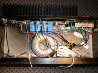
The trafo at the centre of the board is just fine, a toroid has minimal external field at low power anyway, and at high output the amp will still preserve a high S/N ratio. I would always prefer to have the toroid on the other side of the heatsink, but this is not always possible. You can secure peace of mind with a thin, ferrous metal shield between the filter caps and the toroid, however, that's always a useful option.
My thanks to the mods for removing the OT posts, including some of my own, during my beauty sleep. Nothing quite like a happy ending!!
Now, we await John's comments on the quality of the sound. That, after all, is the object of this whole process - not the Copernican bunfight......
Hugh
Thank you mods
Now a question: Is this xmfr too close to the pcb & should I mount it on the right hand side which is where the speaker outs & PS in are?
Hi Jkeny,
Personally I'd say leave it where it is. I do have problems with toroidal induced noise on my series 200, though it is probably worse because the toroid is under the pcb. (I know it is noise from the torroid, because a lead sheild cuts it a lot, and taking it out of the case completely removes the noise). It is under the right channel and the noise on the right channel is worse, which is why I suspect in your case putting it in the center radiating towards the PS is probably better. I would think the PS would be less lilkely to pick up noise than the amps.
If you do find problems you can try rotating the torroid, I've been told that they don't necessarily radiate evenly and that rotating them can send the emi away from the circuit (not sure if this is correct or not).
The torroid in my Chip AMP is VERY close to the chips but I have no problem with noise at all, the orientation though is that the p2p amps are at right angles to the torroid which is mounted vertically.
Tony.
Last edited:
Thanks Hugh & Tony,
Yes another option, if needed, would be to mount the toroid on it's side at the front panel but we will see how this configuration sounds first. I'm waiting until tomorrow to apply power as I'm tired now & I want to start fresh in the morning with the sound.
Yes another option, if needed, would be to mount the toroid on it's side at the front panel but we will see how this configuration sounds first. I'm waiting until tomorrow to apply power as I'm tired now & I want to start fresh in the morning with the sound.
Member
Joined 2009
Paid Member
Toroid EMI
A quick suggestion on toroidal installation: Convention has it that the area from which the leads exit is the highest radiator of EMI. It is also encouraging to be able to just rotate a jury-rigged trafo to the lowest measured hum position.
However, unless you have adequate safety precautions and good nerves, locating this side and the diode leads to their furthest point from the amp's input stage and signal wiring will also have a very good chance of avoiding obvious EMI.
Hi folks,If you do find problems you can try rotating the torroid, I've been told that they don't necessarily radiate evenly and that rotating them can send the emi away from the circuit (not sure if this is correct or not).
.
A quick suggestion on toroidal installation: Convention has it that the area from which the leads exit is the highest radiator of EMI. It is also encouraging to be able to just rotate a jury-rigged trafo to the lowest measured hum position.
However, unless you have adequate safety precautions and good nerves, locating this side and the diode leads to their furthest point from the amp's input stage and signal wiring will also have a very good chance of avoiding obvious EMI.
Last edited:
this is worth doing......................able to just rotate a jury-rigged trafo to the lowest measured hum position.
A dmm set to mVac and the input RCA fitted with a shorting plug shows this up.
Your transformer leads look like solid core. Better if they are flex leads, more flexible and resistant to breaking.
But do make sure the mains connections are well insulated.
Member
Joined 2009
Paid Member

- Status
- This old topic is closed. If you want to reopen this topic, contact a moderator using the "Report Post" button.
- Home
- Amplifiers
- Solid State
- New Aksa Amplifier build pics - Naksa