Oh yes, and there are more to come! Welcome Welcome!
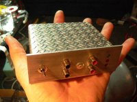
I've just really started to listen to AMP9 and it keeps surprising me, what a wonderfull amp....sigh.... Showed it to my collegues yesterday and they were really surprised again by the enormous power from such a small box...'so there are two stereo amps in there?! Waaow!' Tomorrow (if there's time) I will connect some PA speakers at work, one of my collegues insisted upon doing this test...
I've just recently upgraded my subs at home a bit and will test AMP9 in parallel on them soon..(I have three TAA4100A-based amps at the moment..two can drive my speakers at home, one in my car if it performs well in parallel. otherwise I'll sell one to a friend...my car will have an SMPS-driven AMP5 or two AMP11 in the near future....)
AMP11
Hi,
I assembled AMP11.
However, the amplifier does not take the trouble of moving as it thinks.
LED of fail and mute were lighted
When I touched the land of R52(IC side) by the human body, LED turns off and the sound came out normally.
Also, LED turns off when I touch VPPSENSE of TC2001 with the tester and the sound came out normally.
It's hard to say what exactly is going on from here, but I think it is a bad connection or bad soldering somewhere. Make sure the status of the led should be 'normally-on' or 'normally-off'....
AMP11 is not for beginners, it uses mainly SMD components...to have a go at some 'easier' amps first can teach you what to look for when problems occur...
-Is the chip well aligned?
-Did you measure all connections to the chip legs for conductivity or short cuts?
-Are all components placed correctly? (+ and - for caps, diodes, and no exchanges...)
-Did you rinse all solder flux contamination off the board, especially around the chip legs? (use alcohol and a tooth brush for instance)...
You can use a strong spotlight to hold the board against to see the leads/connections better...
Go over it and go over it.....and go over it again....
Use your dmm wisely...
I removed C1 and J5.
However, two terminals of C1 seem to be connected to GND.
Each bill solder is being confirmed with the magnifier with the tester.
However, I am not able to discover the differences in two amplifiers.
And, the check of the circuit during the output I have short-circuited and there is not the reaction of one AMP11.
I seem to have crushed IC.
I doubt it, I thought this many times during the construction of lots of AMP32 kits....In the end I had them all working, this is a very good SMD-amp to start with by the way...
I think the chip won't be damaged from short circuiting the output, all Tripath amps I've tried are well protected against this... Did you install an overload led? Normally only the led will burn when the outputs are shorted and the amps switches itself off, I think you made a short circuit somewhere. Than also the amp will never produce sound, it will remain in 'protection mode'.... My suspicion gets stronger because you measure a connection between both pads of C1 to ground, this seems odd to me....
To get this straight, I've never built an AMP11 myself... I do intend to as it seems like a very fine amp...
Maybe you can ask Jan from 41hz for more specific information....open a customers support thread, he does answer these! Or start with a thread at the 41hz forum, Jan would prefer you to do this first...
I'm getting into the instruction manual of AMP11 and datasheet of TK2050 to see if I can find out more, maybe I even find something helpfull...")
Good luck for now!
I think the chip won't be damaged from short circuiting the output, all Tripath amps I've tried are well protected against this... Did you install an overload led? Normally only the led will burn when the outputs are shorted and the amps switches itself off, I think you made a short circuit somewhere. Than also the amp will never produce sound, it will remain in 'protection mode'.... My suspicion gets stronger because you measure a connection between both pads of C1 to ground, this seems odd to me....
To get this straight, I've never built an AMP11 myself... I do intend to as it seems like a very fine amp...
Maybe you can ask Jan from 41hz for more specific information....open a customers support thread, he does answer these! Or start with a thread at the 41hz forum, Jan would prefer you to do this first...
I'm getting into the instruction manual of AMP11 and datasheet of TK2050 to see if I can find out more, maybe I even find something helpfull...
Good luck for now!
- Status
- This old topic is closed. If you want to reopen this topic, contact a moderator using the "Report Post" button.
- Home
- Amplifiers
- Class D
- new 41hz stuff? amp9 & amp11