No. After investigating the Never Connected desing I came up with these results:
-The Never Connected PS is using a short conduction angle rectifier to charge a cap, then this cap is used as a supply reservoir for the Standard Michell DC power supply using a LM317 regulator. Nothing really fancy there, no speed regulation.
-The Michell DC motor needs a small current, about 75ma. The conduction angle of a low current rectifier supply is small anyway. So a normal rectifier in this application will behave as a NC supply.
-Others users commented than a low impedance supply (big transfo), low ESR Caps, Fast recovery diodes, CLC filtering and Low Dropout Regulator will probably give equivalent, if not superior results than the NC Supply.
-In particular the CLC filtering gives superior supply capacity. This principle is rarely used because choke are expensives.
-The Michell supply provides only 1 speed. My supply provides 2.
So my ver 1.0 is the first version of the upgrade supply. A possible version 2 will add a Back EMF motor speed regulation. I may try to add this functionnallity in this version 1.0 PCB using a daughter PCB, or redesign a complete new one and compare the listening impressions.
Bye...
The prototype is working perfectly with the Tecnodec DC motor. The two speeds selection, the very low supply noise and speed stabilty (using my strobe).
I can't still listen to it
Still waiting to get my tonearm (ordered) and cartridge
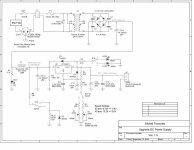
Here the final schematic with reference voltages. I added R8 (330R) to drop the relay supply voltage to 12V.
I can't still listen to it
Still waiting to get my tonearm (ordered) and cartridge
Here the final schematic with reference voltages. I added R8 (330R) to drop the relay supply voltage to 12V.
Attachments
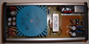
The ver 1.0 is completed. Here the images. First the top view showing the complete PCB mounted into the Hammond case.
On the front are the first section of the supply, rectifiers, first Caps of the CLC filter and the controls: Power-On switch with integrated Power-On Led and the speed selection switch with its two leds. Everything is modular and mounted on sockets so the pcb access and removal is easy.
In the middle section, we can see the big 50VA Telema power transformer and the Hammond DC 156L choke
Then on the back the last section of the CLC filter caps and the LT1085 regulator, the speed selection resistors relay and the 2 multi-turns potentiometers for the speed fine adjustement.
We can see also the power entry module with the integrated EMI filter.
Attachments
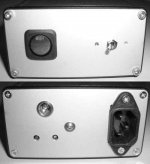
Finally, the front and back panels views. I'll add identification stickers in a few weeks, but for now it is not to bad for something hand made
On the back panel we see the two MT pots access holes, the Michell small DIN connector and the AC socket. The small screw in the middle hold the regulator to the back panel.
On the back panel we see the two MT pots access holes, the Michell small DIN connector and the AC socket. The small screw in the middle hold the regulator to the back panel.
Attachments

OK guys, I know this thread is extremely old, but I am interested in the not-connected power supply (or "battery simulator"). Incidentally I had this idea a long time ago (like many of you) and it seems someone patented it, lol.
Anyway here is my take on the concept :
One transformer and rectifier bridge (not shown) charge a standard reservoir cap. This is modelled by battery V1 and the leftmost switch.
This switch is closed at the beginning of the simulation (to have C2 charged to the correct voltage) and immediately opens, leaving C2 the only source of power.
C1 (right) is the "end-user" cap which we want to charge. I start the simulation with C2 charged to 19V by source V2 ; the switch between these two also opens at the beginning of the simulation.
Note that I don't start with C1 discharged : during normal use, ripple on C1 will be at most a few volts so it is realistic to start with those voltages.
So, at the beginning of the simulation, C2 is charged to 20V, C1 to 19V, both switches are open, and the voltage on the MOS' gate is 0V, so it is not conducting.
When we want to charge C2, we raise the MOS' gate voltage to the proper value and it conducts. This starts just like a switchmode power supply. Current in the inductor quickly raises. Soft switching should be used ; switching losses will be small since current is 0 at the beginning.
Here we need a rather large inductor, making this an extremely slow switchmode power supply.
However, since V=Ldi/dt, as C1 charges, the voltage differential on the inductor drops, and as C1 starts to have more voltage on it than C2, current in the inductor starts to diminish. So, the current in the inductor will look like the top half of a sinewave.
If we don't do anything here, the current in the inductor would reverse and it would start to oscillate, since the MOS can conduct both ways.
So, at the right moment, when current in the inductor is close to 0 but still positive, the mosfet "applies the brakes". We gently drop the gate voltage to 0, so the MOSFET (which acts here as a source follower and not a switch) gently brings the left end of the inductor to ground (in about 1-2 ms).
Since this makes the voltage on the inductor more negative than it was, the current in the inductor has a tendency to reverse quicker.
While we do this, the inductor tries to fight it, however when the inductor current reaches 0, stored energy in the inductor is 0 too, so the MOS regains control, switches off, and inductor current stays at 0.
The diode never conducts, its purpose is to prevent stuff from smoking. C3/R4 are here for snubbing oscillations, but they're actually rather useless since we use very soft switching.
Losses are very small, since the MOS switches when the inductor has near zero current in it.
To make several isolated power supplies from this, we use only one inductor, transformer etc (the expensive parts) and we add 2 MOS switches in the power & ground before C1. So we can charge all the capacitors for the various power supplies in turn.
So we can make several power supplies, isolated between each other, and isolated from the mains, including the crap that goes through the transformer, for a cheaper price than before !
Since the main capacitor C2 will charge every 10 ms from the mains, we have time to charge one "user" capacitor every 10 ms ; so iif we make 4 power supplies from this, the caps will be recharged every 40 ms. There will be more ripple, but I guess this is acceptable.
Anyway here is my take on the concept :
An externally hosted image should be here but it was not working when we last tested it.
One transformer and rectifier bridge (not shown) charge a standard reservoir cap. This is modelled by battery V1 and the leftmost switch.
This switch is closed at the beginning of the simulation (to have C2 charged to the correct voltage) and immediately opens, leaving C2 the only source of power.
C1 (right) is the "end-user" cap which we want to charge. I start the simulation with C2 charged to 19V by source V2 ; the switch between these two also opens at the beginning of the simulation.
Note that I don't start with C1 discharged : during normal use, ripple on C1 will be at most a few volts so it is realistic to start with those voltages.
So, at the beginning of the simulation, C2 is charged to 20V, C1 to 19V, both switches are open, and the voltage on the MOS' gate is 0V, so it is not conducting.
When we want to charge C2, we raise the MOS' gate voltage to the proper value and it conducts. This starts just like a switchmode power supply. Current in the inductor quickly raises. Soft switching should be used ; switching losses will be small since current is 0 at the beginning.
Here we need a rather large inductor, making this an extremely slow switchmode power supply.
However, since V=Ldi/dt, as C1 charges, the voltage differential on the inductor drops, and as C1 starts to have more voltage on it than C2, current in the inductor starts to diminish. So, the current in the inductor will look like the top half of a sinewave.
If we don't do anything here, the current in the inductor would reverse and it would start to oscillate, since the MOS can conduct both ways.
So, at the right moment, when current in the inductor is close to 0 but still positive, the mosfet "applies the brakes". We gently drop the gate voltage to 0, so the MOSFET (which acts here as a source follower and not a switch) gently brings the left end of the inductor to ground (in about 1-2 ms).
Since this makes the voltage on the inductor more negative than it was, the current in the inductor has a tendency to reverse quicker.
While we do this, the inductor tries to fight it, however when the inductor current reaches 0, stored energy in the inductor is 0 too, so the MOS regains control, switches off, and inductor current stays at 0.
The diode never conducts, its purpose is to prevent stuff from smoking. C3/R4 are here for snubbing oscillations, but they're actually rather useless since we use very soft switching.
Losses are very small, since the MOS switches when the inductor has near zero current in it.
To make several isolated power supplies from this, we use only one inductor, transformer etc (the expensive parts) and we add 2 MOS switches in the power & ground before C1. So we can charge all the capacitors for the various power supplies in turn.
So we can make several power supplies, isolated between each other, and isolated from the mains, including the crap that goes through the transformer, for a cheaper price than before !
Since the main capacitor C2 will charge every 10 ms from the mains, we have time to charge one "user" capacitor every 10 ms ; so iif we make 4 power supplies from this, the caps will be recharged every 40 ms. There will be more ripple, but I guess this is acceptable.
Simulation results :
An externally hosted image should be here but it was not working when we last tested it.
I suppose the acid test has to be - is it possible to arrange significantly lower noise injection via this whole elaboration, as compared with using a 'simple' linear supply with a little attention paid to series R and/or snubbing?
While the 'flying capacitor'idea is neat in conception, the little issues you identify, such as avoiding ring-off in L1, make the implentation of an effective NC supply far from trivial.
I also have small reserations about the excess RFI (via higher peak currents) that may be generated at the raw supply side in order to be able to draw sufficient load current on the far side of the series RL and snubbing. Noise feed-through problems IMO are rather like a waterbed - you push down here and it pops up over there instead. ( I had a brief play with the NC idea and settled instead for modifying my existing PSUs and equipment to be as agnostic as possible towards the raw input.) I'm happy to be in error, of course!
Yeah, this is the acid test. The answer is that I have no idea. It is true the concept is seducing but the implementation is a nightmare.
If the same inductor is used to charge several caps, to make several isolated rails, this would be less expensive than using several transformer and bridges. But in this case, since it takes close to 10 ms to do the charging (or else you get a real SMPS), ripple is worse than in a standard power supply. If one switcher and inductor is used per rail, it becomes really expensive since the inductor must be quite large.
I simulated also another concept, which is the flying cap, I mean 2 caps, exchanging roles 100 times a second, one is charging while the other is discharging into the user circuit.
This is actually a lot trickier to get right, because at some point both caps end up being connected together and the more charged one dumps current into the less-charged one and you get a large current spike, not to mention it makes the whole thing useless, since in that case you might as well charge a secondary cap from a primary while the transformer is not dumping current into it.
So you can put diodes to prevent caps exchanging current, but in this case the user circuit sees a nasty voltage spike when the less charged cap is exchanged for the more charged one.
I guess the more interesting thing to do would be to understand why transformers and mains quality can influence the sound.
I mean, you can read really crazy explanations about that stuff. Like a mains filter worsening the sound because "it slows the current draw from the mains". Duh, that is utter crap.
Let's ignore for the moment stuff like rectifier noise etc, this is pretty easy to understand (injecting spikes into audio supply = bad) but let's focus on :
- On a power amplifier, a bigger (over-specced) transformer might sound better even though the amp is not being used remotely close to its max rated power.
- On low power gear (preamp, DAC...) some transformers may sound different than others.
Question is, why ?
Is it some interference that is CREATED by the trafo + rectifier combo ? In this case it is pointless to compare transformers without properly damping and snubberizing the diodes according to each trafo, since differences in inductance and capacitance will influence the rectifier noise (LC oscillations etc)
Is it simply the magnetic field created by the trafo ? (put it in another box)
Or is it some crap that comes from the mains and that some transformers attenuate better than others ?
The time during which the diodes conduct is the same regardless of trafo power. So this doesn't count.
I guess the first thing to do is to rig up a network analyzer to measure the transmission of common mode and differential mode interference from the mains through the transformer.
Problem is, this is a pretty hard thing to do since the transfer functions depend on wether the diodes conduct or not...
First one to suggest a protocol gets all my esteem, lol
Good thoughts all... one thing that I have always wondered: why is the transformer only ever considered as an inlet, a one-way device. It's not, by definition: to what degree does the mains transformer then affect the ability to 'sink' noise INTO the mains network's low impedance?I guess the more interesting thing to do would be to understand why transformers and mains quality can influence the sound.
I mean, you can read really crazy explanations about that stuff. Like a mains filter worsening the sound because "it slows the current draw from the mains". Duh, that is utter ****.
Let's ignore for the moment stuff like rectifier noise etc, this is pretty easy to understand (injecting spikes into audio supply = bad) but let's focus on :
- On a power amplifier, a bigger (over-specced) transformer might sound better even though the amp is not being used remotely close to its max rated power.
- On low power gear (preamp, DAC...) some transformers may sound different than others.
Question is, why ?
So - a supposition: power amps, under load , impose the greatest ripple on their rails of all your examples, and the high charging pulses create the most noise. Perhaps one of the benefits of an 'oversize' transformer then is that the higher leakage capacitance (and reduced leakage inductance of a well-wound toroidal) works well in sinking some of this secondary-side sh*t into the mains. Valve amps, with their low current peaks (esp with choke-input supplies) are happy with regular E-I iron - as are the othe rlow-draw items.
Perhaps this idea also plays a part in the inconsistent results people get from playing with mains filters. If you daisy chain a bunch of devices with undefined and ill-considered impedances, funny things will happen (and given the mains networks significant inductance, I speculate these are in the AF band, and audible.
Agreed. Otherwise it's about uncontrolled, as, say, recommending generic opamp swaps in CD players...Is it some interference that is CREATED by the trafo + rectifier combo ? In this case it is pointless to compare transformers without properly damping and snubberizing the diodes according to each trafo, since differences in inductance and capacitance will influence the rectifier noise (LC oscillations etc)
First one to suggest a protocol gets all my esteem, lol
Snigger. For a start - safely coupling to the mains to take measurements is not a trivial DIY task...
- Status
- This old topic is closed. If you want to reopen this topic, contact a moderator using the "Report Post" button.
- Home
- Source & Line
- Analogue Source
- Never Connected HR Supply circuit