rherber:
>If the qualification were "not connected to the ac supply while any storage capacitor is supplying the load" then I can see some argument can be made.<
When I discussed this power supply concept with Isao Shibazaki prior to the actual design, "not connected to the AC supply while any storage capacitor is supplying the load" was indeed the goal. So I am not quite sure what your point is.
Please feel free to post your own design for an improved (or completely different) circuit which incorporates what _you_ feel should be the key points for a power supply that would qualify for the "Never-Connected" nickname.
Looking forward to the clarification,
jonathan carr
Sometimes I wonder why I bother...
Firstly the NC supplies are not high frequency, they are mains frequency. They don't use inductors like most SMPS and are probably closer in concept to switched capacitor supplies.
Anyone who has experience of these will realise that EMC problems are much less of an issue than with most SMPS topologies.
Anyway, it sounds like some of you (rherber in particular) need to brush up on your basic PSU theory first; start to consider the conduction angle in your traditionally rectified supplies and you'll soon realise that for low current applications (as the NC's are appropriate for) the amount of time your kit is actually connected to the mains is a few degrees of every mains cycle, dependant upopn current drain and reservoir size.
Now start to analyse the noise present on the mains / raw DC supply and consider why it is there and the conceptual idea behind the NC's becomes obvious.
I have no commercial connection here, but can only relate the experiences that I have related to me, that these supplies bring something (sonically) that has been unavailable via other means.
This being DIYAudio I understand the desire to DIY, but the criticism of prices should be kept seperate from the discussion about technical issues. Some of you obviously have no concept of the economics of low-volume specialist audio products!
Personally those prices aren't that great if the R&D behind the concept is significant. Anyone who believes they can make a living in audio at 'cost plus' is deluding themselves.
Let's curb the cynicism and have a decent technical discussion, better still buy one of the bloody things and then report back - you can NEVER know how well the NC concept works, without actually trying it in the way the designer implemented and intended it.
Too many of you think that you can build a circuit from a schematic and it will always perform identically, this is far from the truth, as anyone with actual experience in these issues will tell you (Charles / Hugh?).
As Werner points out the technical details of the supplies are undisclosed, although the concept is clearly explained in the Colloms review in my view. I'm not privy to this information either, but I have every intention of trying these out in the not too distant future.
Based on the opinions of those whose views I trust, I could spend a lot more, for a lot less, sonically. Since they offer total forward and reverse isolation to the mains supply, there are some hidden cost benefits too.
I use a number of external supplies to feed various elements of my system. Currently each has to have its own transformer, for isolation. The NC eliminates this necessity and opens the way for me to have every single supply running from a single transformer without any loop / crosstalk issues - this has potential cost and 'elegance' benefits ; factor this in too, when considering the prices.
Andy.
Close, but no cigar
Change this to: -
Peter, the whole point of the claim made for the NC technology is that it is somehow better than other PSU's because the load is never connected to the mains supply
and you'd be correct.
Peter, the whole point of the claim made for the NC technology is that it is somehow better than other PSU's because it is "never connected" to the mains supply.
Change this to: -
Peter, the whole point of the claim made for the NC technology is that it is somehow better than other PSU's because the load is never connected to the mains supply
and you'd be correct.
How about a cynical technical disscusion?
"Let's curb the cynicism and have a decent technical discussion, better still buy one of the bloody things and then report back - you can NEVER know how well the NC concept works, without actually trying it in the way the designer implemented and intended it."-AWL
I hope that nobody thinks that Andy is encouraging anyone to reverse engineer the design. I am sure he is not. I think the concept is very clear about the circuits intention. Mr. Carr's schematic seems like a pretty good way to implement the idea and here is another one. Some of the ideas in this circuit could be applied to Mosfet synchronous rectifiers which could be as important sonically as decoupling the two caps with the proposed circuit. Synchronous rectification is very widely used in switching power supply design and could bring some of it's advantages in RF noise reduction and low switching losses to 60/50 Hz supplies. I have a design for that as well but will sit on that one while this circuit is being analyzed. I probably won't answer a lot of questions now to keep from muddying the water during an objective look at the design by others. Remove D6 connection to ground. R2 can be connected to D# to D6 to chagne voltage threshold. Let the rock throwing begin.
Attachments
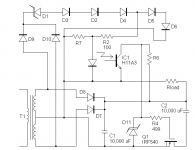
Gee, Fred, do you think you could draw the circuit inside-out next time? ")
I don't know if I got mixed up or you got mixed up, but here's how it looks to me:
1) C1 is "always connected" to the transformer.
2) Half of C2 is "never connected" to the transformer.
3) Rload is "always connected" to the transformer.
Seems to me that #3 nullifies the point of the exercise... or maybe I'm just missing something.
Thanks,
Charles Hansen
Edit - This was written before your correction was made.
"never connected "
I've never seen a schematic for such a supply, "never connected", that is. I am, however familiar with "buck-boost" dc-dc converters, and transformer-isolated flyback converters. With these two converters, the input and output are never directly connected. During the power switch PWM on time, the inductor, or flyback transformer is increasing in energy, while the output filter cap is supplying the load on its own, disconnected from the input by the back-biased diode. During the power switch PWM off time, the inductor or flyback transformer is disconnected from the input, and de-energizes into the output load, and filter cap. Hence, the input never directly transfers energy to the output. With boost converters, popular for power factor correction front ends, the input directly transfers energy to the output during the off time. With buck converters, and all transformer-isolated forward converters (simple forward, push-pull, half bridge, full bridge), direct transfer takes place during the on time. A PFC front end using the buck-boost or transformer-isolated flyback topology instead of the more common boost topology could claim to be never connected. Maybe this is what is meant by "never connected". Again, I'm just venturing a guess. Maybe it's something else. Best regards.
I've never seen a schematic for such a supply, "never connected", that is. I am, however familiar with "buck-boost" dc-dc converters, and transformer-isolated flyback converters. With these two converters, the input and output are never directly connected. During the power switch PWM on time, the inductor, or flyback transformer is increasing in energy, while the output filter cap is supplying the load on its own, disconnected from the input by the back-biased diode. During the power switch PWM off time, the inductor or flyback transformer is disconnected from the input, and de-energizes into the output load, and filter cap. Hence, the input never directly transfers energy to the output. With boost converters, popular for power factor correction front ends, the input directly transfers energy to the output during the off time. With buck converters, and all transformer-isolated forward converters (simple forward, push-pull, half bridge, full bridge), direct transfer takes place during the on time. A PFC front end using the buck-boost or transformer-isolated flyback topology instead of the more common boost topology could claim to be never connected. Maybe this is what is meant by "never connected". Again, I'm just venturing a guess. Maybe it's something else. Best regards.
Interesting circuit Fred!
Charles, as Fred mentioned, the load should be across C2, not as shown in his schematic.
It's elegant though, C1 looks conventional, it is connected to T1 during the conduction period of the rectifiers, which will depend upon load (and will be a small part of the mains cycle, at low load currents).
C2, whilst it looks always connected, loses it's ground return path for the period the opto is on, which is related to the peak of the AC waveform and the subsequent drop in the diodes. The opto / diode chain therefore acts as a comparator.
If one sets the threshold here to the right point, it then removes the ground return path (via Q1). This is biased on by the smoothed DC, until the switching threshold is reached, and IC1 turns off Q1. This is also quite a soft switching action, so should helpe reduce HF noise within the system.
By this mechanism C1, can charge and whilst the rectifiers are connected to the load and forward biased, no current can flow into the load from them, since the return path is missing. I'm not sure it qualifies as 'Never Connected' in the same sense, but it certainly disconnects load from the raw supply over the noisy part of the mains cycle.
It's definitely interesting and simple enough to build and listen to - anyone have some time on their hands?
Andy.
Never say never
" I'm not sure it qualifies as 'Never Connected' in the same sense, but it certainly disconnects load from the raw supply over the noisy part of the mains cycle."
Andy has got the basic outline of the circuit correct. I am not suprised, he is a sharp guy. This circuit was actually to emulate the function of the circuit that Mr. Carr posted. With a few more parts the load and both terminals C2 could be isolated during the charging phase of C1. The hot terminal instead of ground could be broken for C2 with a similar circuit. "Never connected" would use fet switches to both terminals of C2. The circuit can be redesigned, for full wave rectification and a non CT transformer, with a couple of diode bridges (hint one of them is a low power one). "Never connected" is actually a misnomer since there is still a high impedance connection through the diodes in their reversed biased state and mosfet in its
off state. More importantly perhaps is the device capacitance path for high frequency noise. Now if one combined large relays with the soft switching mosfets.............
F.r.e.d.l.y
PS I think mosfet synchronous rectification for the for the first filter cap is also benificial, with or without the NC circuit. Thanks to SN for the advice about never showing too detailed a circuit (and maybe a couple of mistakes to slow the rip off artist down....) and absolutely
not showing the best or latest one.
Re: Never say never
Fred, you are probably old enough to remember the *other* kind of vibrators.
You know, the kind they used in car radios to generate plate voltages from a car battery.
I used to play around with them as a kid. When you hooked them up to an ignition coil and a battery, you could make nice sparks!
Anyway, someone recently told me that the vibrators were connected in such a way as to disconnect the system completely from the car's electrical system when the capacitor was discharging. Kind of like a *reverse* "Never Connected" so that the noise of the vibrator/transformer wouldn't propagate back into the car's electrical system. I don't know if this is true or not, but if it is then your idea about "large relays" is old hat!
Cheers,
Charles Hansen
Fred Dieckmann said:Now if one combined large relays with the soft switching mosfets...
Fred, you are probably old enough to remember the *other* kind of vibrators.
You know, the kind they used in car radios to generate plate voltages from a car battery.
I used to play around with them as a kid. When you hooked them up to an ignition coil and a battery, you could make nice sparks!
Anyway, someone recently told me that the vibrators were connected in such a way as to disconnect the system completely from the car's electrical system when the capacitor was discharging. Kind of like a *reverse* "Never Connected" so that the noise of the vibrator/transformer wouldn't propagate back into the car's electrical system. I don't know if this is true or not, but if it is then your idea about "large relays" is old hat!
Cheers,
Charles Hansen
And it relay relay works.........
"I don't know if this is true or not, but if it is then your idea about "large relays" is old hat!
Maybe the NC gimzo patent is prior art then. I was being tounge in cheek about the relays and did not remember the vibrator voltage step up. Kind of like a crude switching power supply when you think about it.
jcarr said:Technics' "Virtual Battery" refers to a particular way of applying the voltage reference for a voltage regulator, and does not refer to the actual power source to the regulator.
OK, I finally found the reference for this. From a 1999 Panasonic press release announcing the world's first DVD-Audio players (Panasonic DVD-A7 and Technics DVD-A10), the following is described:
"While the Panasonic DVD-A7 provides extraordinary audio and video quality, the Technics DVD-A10 is a step above and designed to address the needs of discriminating audiophiles. For example, to complete an uncompromising design, the audio power supply in the DVD-A10 incorporates a system called Advanced Virtual Battery Operation. Using a capacitor to supply its charged power to the audio reproduction circuitry, the technique simulates a battery (pure source of DC current) to virtually eliminate power supply "noise'' for faithful reproduction of even the smallest signal information."
Sure sounds similar to the "never-connect" technology to me...
I read through this thread and found the discussion interesting. However even though there is no "direct connection" to the line there is a lot of coupling through the power supplies in all of the variants I have seen (with one exception). If the capacitive coupling were not a major issue a decent transformer would be the end of the problem. However sigificant noise can be found on the AC line up to well over 1 MHz and into the 10s of MHz.
Adding a lot of circuitry with major switching transients is not much of a fix. Implementing a design with SCR's and opto isolators will get closer but an off semiconductor is still a leakage path. I like the vibrator idea, however its noisy and you still need twice the caps to get there.
I have another idea (I first proposed to JCarr among others years ago) that is real isolation. Its very simple and has the further virtue of being the least effencient supply imagineable. Simply use a large light bulb (100W or so) to illuminate a solar panel (good for a watt or two). The isolation is very large. It gets better the further apart the two are but you lose output fast. The supply for the light bulb can be regulated to make it more interesting. I don't think this has commercial value since it is the antithesis of energy star but it would work for a low power load.
-Demian
1audio said:Simply use a large light bulb (100W or so) to illuminate a solar panel (good for a watt or two).
I love it!
A Densen and an LC Audio. Both phonostages.
An externally hosted image should be here but it was not working when we last tested it.
Lars' concept with "optocoupler" is rather rare. I wonder why?
Larger picture here
http://www.lightball.dk/pics/riaa03-1.jpg
The NC supply is like reading a front panel of a japanese amp "dual servo class A action loop control" etc. many words but what is it and what does it mean?
How much improvement can you achieve with this NC thing compared to a regular well designed PS? If you don't use Lars' approach with really small stray caps (possible at least) you have always stray caps through the transformer and the connection from the signal sources. Maybe an "ormoljevarning"
(orm = snake)
Today, nearly all consumer TV-sets and VCR/CD/DVD players use flyback type switching mode power supplies
The flyback circuit meets at 100% the never connected criteria since the transformer is actually an inductor that is alternatively charged from the primary side and left to discharge to the secondary side [and both actions *never* happen at the same time]
So, effectively, the inductor is never connected at the same time to both sides in all flyback SMPS found in cheap equipment
Knowing this fact, we shouldn't expect more wonders from the 'Never Connected' B***S*** than from those classic cheap flyback SMPS. They are just EMI generators
- Status
- This old topic is closed. If you want to reopen this topic, contact a moderator using the "Report Post" button.
- Home
- Amplifiers
- Solid State
- Never-connected clone?