Just an update that I have got the manual and been able to fix most of the issues with my A1. Only outstanding thing is an issue where the signal generator is 40dB too hot when it is set <-18dB. i.e. it works fine from +22dB down to -17.9dB, then instead of generating -18dB it is outputting +22dB, and this relationship is maintained down to its minimum output level.
I see that one of the relays on the rear vertical backplane board switches in a 40dB attenuation stage so I hope that's the issue but I still haven't been able to work out what's going on. Will update if I fix it.
I see that one of the relays on the rear vertical backplane board switches in a 40dB attenuation stage so I hope that's the issue but I still haven't been able to work out what's going on. Will update if I fix it.
I had a problem where the auto ranging did not work at several levels. Advice from NTI was that the problem was dead capacitors in the relay drive circuits. Replacing them solved the problem. They are located in the front right corner of the PCB. Maybe that will help someone.
I would be grateful if someone could hook me up with the service manual.
Jeff
I would be grateful if someone could hook me up with the service manual.
Jeff
Hi, would It be possible for you to send the manual to me as well? I've got an A1 with a faulty output amp. If anyone else is reading this post please share it! My email is michelesignorinimail@gmail.comHi Mark, thanks for the link. Unfortunately it is only the user manual which I had downloaded before. Luckily another member shared the service manual with me.
Thanks,
Mike
Hello, JSantoro, thank you for your reply. I found the manuals there indeed, but I would need to register in order to download them. Unfortunately, registrations seem to be closed for an unknown time.
Would it be possible to post those manuals somewhere else, please? Could you maybe email them to stof@live.com?
Many thanks!
Would it be possible to post those manuals somewhere else, please? Could you maybe email them to stof@live.com?
Many thanks!
") I'll keep you posted with the results!
I'll keep you posted with the results!Hey, I'm still looking for the manuals and schematics, sadly I'm not an HIFi engine member and I'm unable to access them.
Would it be possible to send them to me as well please? my email is michelesignorinimail@gmail.com
Thank you in advance!
Would it be possible to send them to me as well please? my email is michelesignorinimail@gmail.com
Thank you in advance!
Hi! I've got my A2 working again! It turned out to be a faulty optocoupler in the data-path of the PCM63. There was a signal coming out, but it was distorted and could not comply to the setup and hold times of the PCM.
Another question: I am guessing that the FFT-option is nothing more than an A/D convertor, which is misteriously drawn as a black box on the digital option schematics. Does anyone know the A/D part? It's an 18 bit double channel A/D in a DIP-28 package, that is annotated by "U1028" on the board layout... I would like to give it a try putting in that A/D chip, 2 NE5532 opamps, and enabling the FFT option in the service menu...
Many thanks!
Hello, do you send me SM for A1 and A2? mail: ciasteczkowypotwornie @ gmail.comSent
Rest of my manual is on my ftp: http://bee.mif.pg.gda.pl/ciasteczkowypotwor/
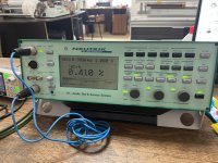
Hi all. I have the following internal measurement result. What could be the problem? If anyone has a service manual A1, A2, please send it to me by email crazynetwork.km@gmail.com Thank you very much!
Attachments
- Home
- Design & Build
- Equipment & Tools
- Neutrik A1 service manual and schematucs