Problem is in the amp then. I know for sure that it's possible to build the amp as a stereo amp and have it be completely quiet, so I'd look at any potential for current to flow in the ground connections to the input of the amp.
Note the little blurb in the design doc that the RCA shell must be isolated from the chassis.
this is spot on. for some reason there seems to be a path for current to flow from chassis to the RCA shield. i used the recommended neutrik nf2d connectors which - i assume - isolate the shield from the chassis. ground connection is also lifted. honestly, i have no idea which path the current takes from chassis to RCA shield. well, i've got a whole weekend to look for it.
please don't feel like a quick answer is needed. i know you've got more important things on your mind.
best,
michi
Just wanted to give a quick update on my progress...
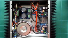
The LM3886DR boards came together very easily and then it was on to putting it all into the chassis. I'm a bit of a "neat-freak" so want this to look good (internally as well as externally) as well as sound good. Lots of planning and this is what I've ended up with (see picture).
The CD cables between the Power-86 and LM3886DR are a bit long, so I may redo those, but other than that, I'm quite pleased at how it has come together. Other than testing, the only remaining chassis job is routing a bit of fibre optic from the Power-86 LED to the front panel.
At this stage, I've powered up the Power-86 and checked voltages but haven't yet applied power to the whole amplifier. I've cobbled together a light-bulb tester for the initial tests, just in case.
Oh, and the hum from the torroid is much smaller now it is screwed down in the chassis, so that's a relief.
Fingers crossed for the moment of truth. Too busy today though so it will be in a few days time...
Attachments
You have two chips on one heatsink and none on the other?Just wanted to give a quick update on my progress...
The LM3886DR boards came together very easily and then it was on to putting it all into the chassis. I'm a bit of a "neat-freak" so want this to look good (internally as well as externally) as well as sound good. Lots of planning and this is what I've ended up with (see picture).
The CD cables between the Power-86 and LM3886DR are a bit long, so I may redo those, but other than that, I'm quite pleased at how it has come together. Other than testing, the only remaining chassis job is routing a bit of fibre optic from the Power-86 LED to the front panel.
At this stage, I've powered up the Power-86 and checked voltages but haven't yet applied power to the whole amplifier. I've cobbled together a light-bulb tester for the initial tests, just in case.
Oh, and the hum from the torroid is much smaller now it is screwed down in the chassis, so that's a relief.
Fingers crossed for the moment of truth. Too busy today though so it will be in a few days time...
i've been using these recently (various colours and values available):
5580501027F Dialight | Optoelektronik | DigiKey
nice plug and play solution and snaps right into a hole in the front panel.
5580501027F Dialight | Optoelektronik | DigiKey
nice plug and play solution and snaps right into a hole in the front panel.
...so I'd look at any potential for current to flow in the ground connections to the input of the amp.
Note the little blurb in the design doc that the RCA shell must be isolated from the chassis. Heed da warning.
Back to the grounding / hum question. I used the continuity check of my multimeter to search for a potential path for current to flow in the RCA shells.
Yes, the RCA shells are properly isolated from the chassis. Yet when I check for continuity between the shells and the chassis the "beep" tells me there's a path. The only one I can find is this one: GND of RCA IN is connected to to the LM3886DR board. GND of the LM3886DR is connected to GND of the SMPS86 power supply. GND of the power supply is connected to the chassis. Thus: There's continuity between the chassis and RCA shell.
But isn't is supposed to be like that? I'm even more confused now

Best,
Michi
You have two chips on one heatsink and none on the other?
Yep, see planning discussion earlier in the thread (starting at post #308). It certainly would have been more symmetrical to have one chip on each side, but laying the chassis out as I have done keeps all of the AC power tightly down the left hand side of the chassis, away from the signals.
I should stress that this is just my thought process - I'm a novice at this type of thing. It remains to see whether it all works!
Yep, probably easier, but I liked the idea of a really small indicator on the front panel. A short length of 1mm fibre optic allows this and is easy to do.Wouldn’t be just as easy to run the power LED on a flying lead, as on the ACA kit?
Back to the grounding / hum question. I used the continuity check of my multimeter to search for a potential path for current to flow in the RCA shells.
Yes, the RCA shells are properly isolated from the chassis. Yet when I check for continuity between the shells and the chassis the "beep" tells me there's a path. The only one I can find is this one: GND of RCA IN is connected to to the LM3886DR board. GND of the LM3886DR is connected to GND of the SMPS86 power supply. GND of the power supply is connected to the chassis. Thus: There's continuity between the chassis and RCA shell.
But isn't is supposed to be like that? I'm even more confused now
Best,
Michi
That logic seems sound to me Michi. Just as a check, if you disconnect the SMPS86 from the chassis, does the continuity beep go away? Not that I'm suggesting this as a long-term solution but it might help to verify your suspicions.
Earlier on Tom suggested lifting the ground. I tried that without success. Although I am not sure if it would be enough to remove the cable that runs from the grounding lug to the chassis. I suspect that the chassis is also connected to ground via one of the mounting screws. Tom, can you comment on that?
I'm not Tom but...
Looking at pics of your build (here ?) and pics of the smps86, you populated R2/R3 on the smps86 board. These seem to tie the earth (r2) and maybe the gnd (r3 ??) to a mounting screw ? A low value resistor will beep on a continuity test.
Another thing: those chassis use anodized aluminum and the connections between the various panels aren't always low impedance. I sand the sections in contact in my builds.
Yes, those are the pictures of my build. R2/R3 are populated with 0r resistors. I assume that's about the same as using a jumper. But i'm not sure what you are trying to tell me :-(
You're absolutely right. The anodizing is super thick. I have sanded it in all critical areas.
Yes, those are the pictures of my build. R2/R3 are populated with 0r resistors. I assume that's about the same as using a jumper. But i'm not sure what you are trying to tell me :-(
Well, nothing more than those r2/3 resistors indeed connect:
- gnd and earth together;
- gnd and earth to chassis through a mounting screw.
So it's totally normal if you have continuity from the rca gnd to earth/chassis if the supply is connected.
edit: the next step, to actually lift the gnd as suggested by Tom to you, would be to remove r3 see if you still have noise (that wouldn't be a long term solution, just a check).
Last edited:
Thanks for explaining!
I was just wondering because Tom mentioned to be sure there isn't a path for current to flow between chassis and RCA ground. Yet that very path is part of the design.
I will lift ground the way you suggested (or by removing the mounting screw) and see where that leads me.
Thanks for your help!
I was just wondering because Tom mentioned to be sure there isn't a path for current to flow between chassis and RCA ground. Yet that very path is part of the design.
I will lift ground the way you suggested (or by removing the mounting screw) and see where that leads me.
Thanks for your help!
Which still doesn't fix the tie between earth and the amp gnd. And that's what you want to lift for a while. So R3 has to go.
In other terms: for safety reasons, you want the chassis to be earthed. So when we say lifting the gnd from the chassis it at first means lifting the gnd from earth.
In other terms: for safety reasons, you want the chassis to be earthed. So when we say lifting the gnd from the chassis it at first means lifting the gnd from earth.
- Home
- Amplifiers
- Chip Amps
- Neurochrome LM3886DR Build