Well, just changing the load resistors will get you far enough.
Hi John
I am currently using 150 Ohm load resistors (10.65ma) and I want to try original value 100 Ohm (16ma) at the input stage.
Don't bother, HKC, you are just making trouble for yourself. It is only the really low Idss devices like the 170GR that really are the wrong part for this project.
Hi John
You suggested on post # 183 of this thread to parallel 2 JFets to increase the idss. You tell different stories now, what's wrong with you?
Last edited:
Low capacitance is better than high current IF you are using a volume control pot, in front of the line driver.
I see, but I noticed some other pre-amps also parallel JFets at the input stage such as Threshold FET 10 line drive. I guess this is the matter of the designer's personal preference and there is always pros and cons in a design. In my case, I can feel the noise level of 2 is much better than 1 single JFet.
For everyone else: The problem with paralleling fets is that they have significant non-linear capacitance that will add MORE DISTORTION to the circuit IF a high source impedance is used, such as a volume control 10K ohm and up. IF you are amplifying a MC cartridge, however with a source impedance under 100 ohm, then paralleling is OK, within reason. This is because of RC You just multiply the expected R with the expected R at the input and compare. IF C is non-linear, then less C is better. The advantage of paralleling j-fets is that they are quieter working as a group, and for an OUTPUT STAGE, you get more current drive. However, for a line amp or a power amp input stage, it is better to use high Idss parts from the same device selection. IF the parts are Toshiba, that means V or violet. This is why I design all of my Vendetta and CTC circuits with V parts. Less capacitance, yet high current. Best of both worlds.
For everyone else: The problem with paralleling fets is that they have significant non-linear capacitance that will add MORE DISTORTION to the circuit IF a high source impedance is used, such as a volume control 10K ohm and up. IF you are amplifying a MC cartridge, however with a source impedance under 100 ohm, then paralleling is OK, within reason. This is because of RC You just multiply the expected R with the expected R at the input and compare. IF C is non-linear, then less C is better. The advantage of paralleling j-fets is that they are quieter working as a group, and for an OUTPUT STAGE, you get more current drive. However, for a line amp or a power amp input stage, it is better to use high Idss parts from the same device selection. IF the parts are Toshiba, that means V or violet. This is why I design all of my Vendetta and CTC circuits with V parts. Less capacitance, yet high current. Best of both worlds.
Hi John
Thank you for the explaination. Another example which parallel JFets too is the Moxtone Lab Balanced pre-amp its' circuitry is very similar to the CTC Blowtorch it uses 2SK170BL and 2SJ74BL in parallel.
To anyone who owns an original authentic JC-2 pre-amp. I can send my clone to him to make an audition. Just want to found out how much better the original JC-2 compare to the clone. Hope knowing the differences between the original and the clone will help to improve the performance of home built amplifiers.
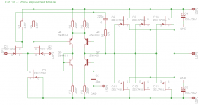
I have increased the output pairs from 2 to 3 and ommited the source
resistors which should give me (almost) 30mA.
I´m not sure yet about the current source of the input stage. I would
like to have slightly more current but I´m not aware of any higher
Idss FETs which have low noise at the same time.
Would any drawback result from using a bipolar current source instead ?
But probably it´s ok anyway...
Attachments
Well that´s what I thought, 50% will probably be ok, I used that before. The reason why I considered more current was post #290 where John said "The JC-2 phono input stage used Siliconix J110 input devices that are high current switches, that usually have an Idss of over 20 ma. The input devices were used at about 15 ma ea for lowest possible input noise. When you change the Id of the input devices in order to use lower Idss types, then you MUST change the load resistors, and this LOWERS the open loop bandwidth."
Lower open loop bandwidth certainly is not a good thing if we can avoid it (to some degree).
Lower open loop bandwidth certainly is not a good thing if we can avoid it (to some degree).
I don´t want to use lower Idss types for the input stage and I don´t run them at 100%. As you can see from the schematic they are at 50% but maybe 70% or so would be preferable for the reasons given in post #290. The output stage FETs are BL and not V, not because I would not prefer V grade but because matched 2SK170V / 2SJ74V are not available any more, this was already discussed in posts #292 and #293.
321#
When circuit simulation I find 1.5Khz appeared in FFT figure ,iuput were 1KHz.
That would be IM distortion frequency ?
But FFT should be harmonics ,it's right?
It's puzzles me.
An externally hosted image should be here but it was not working when we last tested it.
When circuit simulation I find 1.5Khz appeared in FFT figure ,iuput were 1KHz.
That would be IM distortion frequency ?
But FFT should be harmonics ,it's right?
It's puzzles me.
I think you guys are in the right ballpark. All else being equal, with this design, more Idss is better. Running at 50% of Idss or even to 80% is best, the jfet can still put out to more than 100% on dynamic peaks without anything obvious going on. However operating at 0 bias, or 100% is iffy.
The higher Idss part gives you a lower value load resistor that extends the open loop bandwidth. The higher percentage of Idss you bias, does the same thing.
However, a medium Idss part will work OK, if you don't starve it.
The higher Idss part gives you a lower value load resistor that extends the open loop bandwidth. The higher percentage of Idss you bias, does the same thing.
However, a medium Idss part will work OK, if you don't starve it.
- Home
- Source & Line
- Analog Line Level
- Need to build JC 2 preamp