Thanks for the link, I have to spend some time on the article.
What makes the sound quality of the power amp? Most power amps design are very basic and simple. Like the typical schematic I drew, it has so few components.
Regarding to power supply, from what I gather in the last two days here, the main thing is low ripple, stiffer the better. So SS rectifier and using low ESR filter caps......lots of filter caps is the key. Is the OT most important where I should spend the most money?
What make the difference between an amp that sells for tens of thousands to one that is only a few hundreds dollars? I am still trying to understand audiophile amps. In guitar amps, we introduce distortion to give the characteristics of the amp. But I don't think this is true for audio amp, people are looking for minimal distortion and fidelity. People can make a cheap amp with lots of power and very low distortion spec. But that does not translate to a good sounding amp. What makes an amp good sounding? Am I going in circle?
What makes the sound quality of the power amp? Most power amps design are very basic and simple. Like the typical schematic I drew, it has so few components.
Sometimes simple, sometimes not so simple search for the Marantz Model 8b schematic for example
Regarding to power supply, from what I gather in the last two days here, the main thing is low ripple, stiffer the better. So SS rectifier and using low ESR filter caps......lots of filter caps is the key. Is the OT most important where I should spend the most money?
Yes most of it is the transformer. Here in Europe we have Lundahl and Sowter, in the US I don't know
What make the difference between an amp that sells for tens of thousands to one that is only a few hundreds dollars?
Most of the times is the marketing, Sometimes, you really see masterpieces tho
Am I going in circle?
Possibly, but after some time it will make more sense")
Sometimes simple, sometimes not so simple search for the Marantz Model 8b schematic for example
Regarding to power supply, from what I gather in the last two days here, the main thing is low ripple, stiffer the better. So SS rectifier and using low ESR filter caps......lots of filter caps is the key. Is the OT most important where I should spend the most money?
Yes most of it is the transformer. Here in Europe we have Lundahl and Sowter, in the US I don't know
What make the difference between an amp that sells for tens of thousands to one that is only a few hundreds dollars?
Most of the times is the marketing, Sometimes, you really see masterpieces tho
Am I going in circle?
Possibly, but after some time it will make more sense
Last edited:
No reason to spend a lot of money on the OT if you go parafeed. Excellent results are to be had with very cheap standard OTs.
" What make the difference between an amp that sells for tens of thousands to one that is only a few hundreds dollars?"
A logo, a name, a review in a big Audiophool magazine. Or maybe some physical gold on the chassis.
" What make the difference between an amp that sells for tens of thousands to one that is only a few hundreds dollars?"
A logo, a name, a review in a big Audiophool magazine. Or maybe some physical gold on the chassis.
the main thing is low ripple, stiffer the better. So SS rectifier and using low ESR filter caps......lots of filter caps is the key.
I think the #1 thing is low output impedance. Use a simple two MOSFET regulator. Costs pennies to make, and makes a LOT of difference. Nonexistent ripple is a bonus of this.
You can have a PSU with no ripple, that sounds like crap and modulates the B+ with the audio signal because of high impedance.
don't think this is true for audio amp, people are looking for minimal distortion and fidelity. People can make a cheap amp with lots of power and very low distortion spec. But that does not translate to a good sounding amp. What makes an amp good sounding? Am I going in circle?
It matters a lot how that low distortion is achieved. I go with the philosophy that you should operate the most linear devices you can find in a manner that lets the devices BE linear.
Make a small power amp as linear as possible (open loop), and try it out. You'll be surprised at how much power you might actually need.
I just draw out a typical schematic of a power amp. You think this will give me the quality I want? I put in the ultra linear tap for the screen grid because it's my understanding that this is important for hifi. If not, please let me know. I am guessing here. This schematic just serve as a starting point only.
Start with something simple. Don't try to build the very best to begin with, you'll learn along the way.
Parafeed simply means a topology, where there is no DC current flowing in the primary of the output transformer.
In a SE circuit, that would mean having some other plate load, a resistor, a choke or in modern times, a MOSFET gyrator or a CCS. The primary has its other end grounded, and the other is connected to the tube plate (or with modern plate loads, to the MOSFET source) via a suitable capacitor.
Lack of DC current makes any OT perform significantly better. You can use a PP OT in a parafeed SE circuit with no problem.
In a balanced circuit, put the OT between the two anodes (one end via a cap), or with modern plate loads, between the plate loads' sources. OT primary center tap is not connected to anything.
Parafeed simply means a topology, where there is no DC current flowing in the primary of the output transformer.
In a SE circuit, that would mean having some other plate load, a resistor, a choke or in modern times, a MOSFET gyrator or a CCS. The primary has its other end grounded, and the other is connected to the tube plate (or with modern plate loads, to the MOSFET source) via a suitable capacitor.
Lack of DC current makes any OT perform significantly better. You can use a PP OT in a parafeed SE circuit with no problem.
In a balanced circuit, put the OT between the two anodes (one end via a cap), or with modern plate loads, between the plate loads' sources. OT primary center tap is not connected to anything.
Thanks, I just got back from a trip and start reading the gyrator circuit. I understand using parafeed will improve the performance of the OT, BUT do you think it will improve the sound of the power amp? It's all about the sound to me.
I notice people use tube gyrator circuits, you mention MOSFET gyrator, how about using BJT? What is the advantage of each one.
For parafeed, you need two capacitors coupling for push pull. Any requirement for those caps? Using primary impedance of 1K looking into one side of the primary, for -3dB low cut off at 20Hz, I got C=1/(2\pi R f)=8uF. So common 10uF 600V electrolytic cap is plenty. I don't even think ESR is that critical as the primary is 1000 ohm looking into one end. Is this true?
If there is a big improvement in the sound, maybe it's worth the while to do parafeed.
Thanks, I am really learning in the last few days.
In a balanced circuit, put the OT between the two anodes (one end via a cap), or with modern plate loads, between the plate loads' sources. OT primary center tap is not connected to anything.
I am still studying SRPP and gyrator circuit. But I have a question first on this balance push pull circuit. Using gyrator circuit on both sides and CT of the primary is open. The swing is going to be half of the regular push pull circuit.
In regular push pull with CT to +400V and assume the tube saturates at +100V, each plate swing between +100V to +700V. So you get 600V peak swing between the two terminals of the primary.
But with para feed, each side only swing from 100V to 400V, the total swing between the two terminals of the primary is only 300V. Obviously you cannot ground the CT of the primary as the gyrator cannot swing higher than the +B of 400V like a real inductor.
Am I correct? So you would loose power unless you can play with the turn ratio of the OT.
Is it possible to use real inductor as load for the tubes in parafeed design? Can you buy a high current choke easily or use an OT with open secondary and make it behaves like an inductor? I wonder whether the big choke for the florescent tube can work as they are quite big with lots of turns of reasonable sized wires. That would be cheap. Then you can ground the CT of the primary and get the full swing.
Last edited:
I understand using parafeed will improve the performance of the OT, BUT do you think it will improve the sound of the power amp?
Yes.
I notice people use tube gyrator circuits, you mention MOSFET gyrator, how about using BJT? What is the advantage of each one.
MOSFETs are cheap, plentiful and easy to use. They provide both 1) cheapest price 2) best impedance (at least in comparison to tube plate loads). No brainer.
For parafeed, you need two capacitors coupling for push pull.
No. Why do think that?
Any requirement for those caps?
Film cap, best quality you can find in this position. Use Russian for best quality and price.
Using primary impedance of 1K looking into one side of the primary, for -3dB low cut off at 20Hz, I got C=1/(2\pi R f)=8uF. So common 10uF 600V electrolytic cap is plenty. I don't even think ESR is that critical as the primary is 1000 ohm looking into one end. Is this true?
Don't use an electrolytic directly in the signal chain. Not good.
Why use such a low impedance? I use 10k primary impedance. One parafeed cap, on the other end of primary. Center tap not connected to anything.
If there is a big improvement in the sound, maybe it's worth the while to do parafeed.
There is. It improves the OT performance a lot, but most importantly, it allows to have proper near horizontal load lines on the output tubes, significantly decreasing distortion. Also much much lower output impedance to OT improves sound quality a lot. Makes the amp sound fast and have a lot of dynamics.
I am still studying SRPP and gyrator circuit. But I have a question first on this balance push pull circuit. Using gyrator circuit on both sides and CT of the primary is open. The swing is going to be half of the regular push pull circuit.
No. It will be 2x of one tube's swing. Why do you say that?
In regular push pull with CT to +400V and assume the tube saturates at +100V, each plate swing between +100V to +700V. So you get 600V peak swing between the two terminals of the primary.
Forced balanced pair will have a differential voltage swing (that's what the OT sees being between the pair) double that of one tube. Try it out in a simulation and see.
Am I correct? So you would loose power unless you can play with the turn ratio of the OT.
No. Not in the way you describe. It is true that forced balanced parafeed is not the best way to have big big power, but it IS the best way to have no NFB sweet sweet linearity.
Is it possible to use real inductor as load for the tubes in parafeed design?
Certainly it is. With a choke you would gain some efficiency, since you wouldn't need as high a B+.
However, you would lose the low output impedance. And you wouldn't have nearly as good a loadline on the tubes. And with a choke, you have significantly rising distortion in the low registers, and overall it'll be a little bit problematic with the low end frequency response (unless you go big bucks). Gyrator is both cheaper, and provides better linearity and output impedance and frequency response.
Then you can ground the CT of the primary and get the full swing.
I'm sorry but this makes no sense.
Lord of Audio knows I've come the slow way here. But learning is good.
As a thought experiment with learning differential voltage swing, replace the OT primary with a 10k resistor. Forget the cap for simplicity (in AC domain the cap is "not there" if it's sized properly).
Think of the pair as two independent SE amps, working in perfect antiphase.
Now put the resistor between the plates and calculate the current that goes thru it when the voltages peak (other at the top, other at the bottom).
I want to get one or two text book that contain gyrotor and SRPP, also power amp design. You have any suggestion?Lord of Audio knows I've come the slow way here. But learning is good.
As a thought experiment with learning differential voltage swing, replace the OT primary with a 10k resistor. Forget the cap for simplicity (in AC domain the cap is "not there" if it's sized properly).
Think of the pair as two independent SE amps, working in perfect antiphase.
Now put the resistor between the plates and calculate the current that goes thru it when the voltages peak (other at the top, other at the bottom).
Thanks
The reason I said that is because with normal CT to +400V, the plate of each tube swing from +100V to +700V. But with parafeed, the plate only swing from +100 to +400V. The swing is half because the gyrator does not swing above +400V like the the CT OT.No. It will be 2x of one tube's swing. Why do you say that?
Yes, for gyrator, it is double of 300V=600V swing. But in normal CT push pull, you have 1200V swing because each plate swing 600V instead of 300V.Forced balanced pair will have a differential voltage swing (that's what the OT sees being between the pair) double that of one tube. Try it out in a simulation and see.
I thought you use load line to maximize the output power. For EL34, the CT primary is optimized at about 3.5K for HT=+450V. If you use 10K primary, you'll loose a lot of power if you use the same load line concept. Is the method of calculating load line of parafeed different conventional way?Why use such a low impedance? I use 10k primary impedance. One parafeed cap, on the other end of primary. Center tap not connected to anything.
Thanks
Last edited:
The reason I said that is because with normal CT to +400V, the plate of each tube swing from +100V to +700V. But with parafeed, the plate only swing from +100 to +400V. The swing is half because the gyrator does not swing above +400V like the the CT OT.
Ah, now I see what you mean. Yes, with a MOSFET plate load you do need a higher B+. If you have the same B+ as with the choke or OT primary loaded circuit, you will have a lot less voltage swing available.
There are no free lunches. For better fidelity, you need to either make do with less power, or make bigger PSUs. I choose fidelity over power every time.
I thought you use load line to maximize the output power. For EL34, the CT primary is optimized at about 3.5K for HT=+450V. If you use 10K primary, you'll loose a lot of power if you use the same load line concept. Is the method of calculating load line of parafeed different conventional way?
Well sure you can have 3.5k primary impedance, if you have the current to push thru it in pure class A (forced balance can only operate in class A). Nothing to stop you there.
If you have gyrator plate loads, the tubes will have hundreds of kilo-ohms as their load line, regardless of the OT primary. Only thing to worry about is that your balanced pair has the current to push thru the OT primary; a rule of thumb is to choose it so that the current swing doesn't exceed about 70 - 80% of the current that goes thru the CCS tail.
I use 10k because my output stages don't have that much current available, so why use less. Also, the bigger the impedance, the easier it is to find a good (smaller value) cap.
If you are interested or curious, I suggest you try making a small balanced parafeed amp with gyrator plate loads. Use a good, linear triode or double triode, like the 6SN7 or such, maybe a 2C51.
Try and experiment. You might also be very much surprised about the amount of power you need.
Try and experiment. You might also be very much surprised about the amount of power you need.
Thanks you very much. I have in mind using EL34, that's the reason I mentioned 3.5K. I don't get what you said the tubes will have hundreds of kilo-ohms as their load line. My understanding is you find the operating point, then draw from that idle operating point to the bend of the 0 grid curve, then you find the slope for the load resistance value. The Gyrator impedance is very high and is out of the picture.Well sure you can have 3.5k primary impedance, if you have the current to push thru it in pure class A (forced balance can only operate in class A). Nothing to stop you there.
If you have gyrator plate loads, the tubes will have hundreds of kilo-ohms as their load line, regardless of the OT primary. Only thing to worry about is that your balanced pair has the current to push thru the OT primary; a rule of thumb is to choose it so that the current swing doesn't exceed about 70 - 80% of the current that goes thru the CCS tail.
I use 10k because my output stages don't have that much current available, so why use less. Also, the bigger the impedance, the easier it is to find a good (smaller value) cap.
For 3.5K, I calculated the coupling cap is 8uF. I know electrolytic cap has high ESR, but can I parallel a film cap of lower value to a 10uF. Say I parallel a 10uF cheap electrolytic with a 0.22uF, then even with a 0.022uF. I am pretty sure that will ensure low ESR through out the frequency of interest. You think that would work?
The highest voltage PT I have seen in guitar amp is 510V after rectifier. Do you know of any higher?
Thanks you. I am still reading the SRPP, yet to get to the gyrator.
Last edited:
Thanks you very much. I have in mind using EL34, that's the reason I mentioned 3.5K.
I strongly suggest you make smaller experiments first. Furthermore, the EL34 is not very linear triode strapped; choose a tube with better curves, otherwise you will either need NFB or have distortion.
I don't get what you said the tubes will have hundreds of kilo-ohms as their load line.
A MOSFET gyrator plate load will provide some 500k ohm load for the tube. Both tubes will operate essentially in constant current, with nearly a horizontal load line. If the tubes in question have good curves, this makes sure they don't make pretty much any distortion at all.
The OT is not a factor in the tubes' load lines. The tubes "don't see" the OT at all.
The OT sees a differential voltage between the primary ends, and the MOSFETs provide current thru the OT primary. Tubes conduct the same amount of current all the time regardless of signal.
The balance works, because the tail CCS is much much stronger than the plate loads. It wins.
My understanding is you find the operating point, then draw from that idle operating point to the bend of the 0 grid curve, then you find the slope for the load resistance value. The Gyrator impedance is very high and is out of the picture.
With MOSFET gyrator plate loads, CCS tail, and parafeed OT, the OT is not in the tubes' load lines. The gyrator is, with its 500k impedance.
For 3.5K, I calculated the coupling cap is 8uF. I know electrolytic cap has high ESR, but can I parallel a film cap of lower value to a 10uF. Say I parallel a 10uF cheap electrolytic with a 0.22uF, then even with a 0.022uF. I am pretty sure that will ensure low ESR through out the frequency of interest. You think that would work?
It will work in the sense that it will pass audio, but for serious use, completely out of question. You need one single film cap in this position. I recommend MBGO types; cheap and as good as any 'audiophile type', better than most.
The highest voltage PT I have seen in guitar amp is 510V after rectifier. Do you know of any higher?
I built a few amps with regulated B+ of 650 volts. I'm planning (dreamin of) one with 3C24 balanced finals, regulated B+ of 1100 volts. No OT, direct driving electrostatic headphones and speakers...
You don't need a 510V B+. Get some 4P1L and B+ of 310 volts. Or 6SN7 or 2C51 or any good linear triode you may have around. 2C22 make truly excellent output tubes.
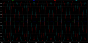
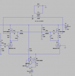
Some picture demonstrations might help my explanation.
These current measurements are from the attached schematic. The two center traces (other one's a bit dim) are the currents thru the tubes, measured from the small resistors right above the tube plates. As you can see, they're pretty much constant; about 50µA swing with a voltage swing of about 70V (individual tube).
So the tubes operate at constant current, variable voltage.
The big swing traces are measured from the MOSFET sources. As you can see, even though the tubes have horizontal load lines, there is some 15mA current swinging thru the OT primary.
MOSFETs swing the current. Tubes handle voltage. Everybody does what they do best! OT is not drawn at all on the tubes' load lines; they are horizontal for maximum linearity and best transparency.
Power is limited by amount of available voltage headroom, and the amount of current a balanced pair passes (both tubes combined).
Attachments
- Status
- Not open for further replies.
- Home
- Amplifiers
- Tubes / Valves
- Need suggestion in building a stereo power amp