Hi all,
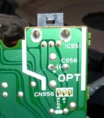
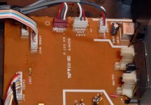
I have an old Sony CDP C8ESD that I've been using as a transport. The optical out crapped out on me the other day. Everything else works fine. I would like to just modify it to take the signal to the optical out to a coax out. It looks to be a simple modification, but there are three wires feeding the torx. Can anyone tell me which two I need to hook to the coax out, gnd and signal. I have attached pics of the board.
Thanks for your help,
PJN
Attachments
One pin is ground, one is supply, the other data. The impedance may be wrong to feed a coax input directly, and is often in any case coupled through a balanced transformer to give a true isolated "floating" output.
Our you sure the transmitter is faulty ? They should be an easy item to source in any case.
Our you sure the transmitter is faulty ? They should be an easy item to source in any case.
")
The bit of extra detail is likely to be true, the signal is less digitally converted,
some data can get lost due to the conversion process.
Data is not lost as such as the receiver has means to detect that. What happens is that optical outputs have worse jitter performance (often a lot worse). They do, however, offer electrical isolation which is a good thing, and especially important if your player is used as a transport and as a player at the same time (on non-transformer coupled cocax digital outputs, this will result in a ground loop if both the digital and analog outputs are conencted at the same time).
Regarding the mod, it is NOT a good idea to drive the coax output directly from a TTL level output pin because the coax input impedance presents a considerable overload for a TTL output. Also, TTL levels are about 7x higher than the standard for coax, and it's only because of the overload condition that the signal level falls within guidelines for the coax connection. All in all, you may end up with a working link, for some time - after which the pin driving the signal on the decoder chip in your CDP will die and you will have a much larger problem. At the very elast a resistive divider is necessary. This will typically be two resistors in series from the TTL output (input to the optical transmitter) to ground, with the tip of the coax taken from the point where the two resistors connect. 75 ohm impedance is standard, and the divider should be 200 ohms from TTL out, in series with 120 ohms to ground. If you can't get 200 ohms resistors, you can use 220 ohms, the resulting impedance is about 78 ohms instead of 75, but it should be close enough. A proper solution would be to add a pulse transformer at the output so it's electrically isolated from the rest of the system.
- Status
- This old topic is closed. If you want to reopen this topic, contact a moderator using the "Report Post" button.
- Home
- Source & Line
- Digital Source
- Need some help with a CD player mod