lineup said:00940
If you know, which I doubtuntil you can tell us with your own words
.. then why not tell me and others.
Why keep your secrets, if you are a sharing DIY Member.
What dicussion would be, if we always reply with a link to somebody who knows better
Actually, I have several great working Regulator circuits using 1nF - 10nF for feedback resistor.
This is why I think you may not be 100% correct.
Regards, Lineup
I don't doubt regulators using 1nf will work. I'm only doubtful about how useful such a low valued cap is. And I'm not keeping any secrets
I just don't see the point to waste my time repeating what others have already said better than I could.This regulator is basically similar to the Sulzer (worse because the reference is coming from the unregulated side). Let's thus quote what ALW has to say about these caps ( http://www.alw.audio.dsl.pipex.com/sulzer_circuit.htm ):
A further enhancement performance is made via the capacitor C3, in parallel with R4. As can be seen, as frequency rises the impedance of C3 drops, in accordance with the reactance of the capacitor (Xc = 1/(2*pi*f*C). This in effect lowers the impedance of the feedback resistor R4 as frequency rises, which in turn reduces the gain of the error amplifier.
This simple trick reduces the noise gain of the amplifier, and hence prevents amplification of any residual noise present at the error amplifiers inputs. It has a further benefit in that it reduces the output impedance of the regulator by a significant margin, further reducing load-related dynamic noise at the regulator output.
Some caveats must be mentioned here though, in respect of error amplifier choice. The amp chosen has to be unity gain stable, or have careful attention to compensation as it's the noise gain not the DC gain that is the relevant parameter for Bode / Nyquist stability of the circuit.
Interestingly the Sulzer regulator is internally compensated to be stable at gains of three or above, but overall stability has been brought about by careful component choice elsewhere, despite the noise gain reduction in the circuit. Be wary though that component substitution may not be simple.
A 100uF or so feedback cap allows us to get a significant increase in performance at low frequencies. With 1nf, nothing serious happens before tens of KHz. The 4.7uf used originally by Sulzer is quite ok in terms of cost/space/effectiveness.
I just wanted to make it clear that the digital power supply board shown in the schematic with the dashed lines is obsolete. I have 3 regulated supplies in its place.
So I'm just dealing with the 5V supply on the board. A+ and D are getting steady +12VDC while A- gets steady -12VDC
So I'm just dealing with the 5V supply on the board. A+ and D are getting steady +12VDC while A- gets steady -12VDC
The part of the schematic that says "digital supply board" that feeds the regulator circuit has been replaced. Everything on the 5v regulator circuit is what we're discussing. I was just making a point that the original ps that fed it was unregulated and relied on the regulator circuit to do everything.
I understand you now, your using pre regulators first
Couple of choices then. Either use the original devices and rebuild it to it's original spec. As these regs are integral to the D/A PCB you are limited with what you can do without major work.
You could still replace all the series pass transistors with IC regulators, and remove the other parts. In your position that's the best option IMO.
It's not just a case of adding more parts. Any design, even something that "seems" as simple as this requires carefull and correct implementation and then testing under all conditions - dynamic and steady state to see how well it performs.
Mooly said:
You could still replace all the series pass transistors with IC regulators, and remove the other parts. In your position that's the best option IMO.
I'm better at analog circuits so please bear with me. Which are the series pass transistors? And which IC reg would you use. When you say remove the other parts (I'm always up for less parts) which specific parts do you mean?
Appreciate the education.
Goto,
http://www.datasheetcatalog.com/
and download the data sheets for LM317 and LM337. Just put those numbers into the blank search box. There are lots of choices, just pick "National" or "ST" as a manufacturer.
The pass transistors are Q1/2/3. It's so easy to fit IC's in their place.
These need two resistors on each to set the output voltage. The data sheet shows how to calculate these, and gives a 5 volt reg as an example.
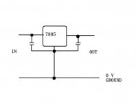
Even easier is to use 7805 and 7905 regs. Again get the data sheets. These need no resistors at all.
http://www.datasheetcatalog.com/
and download the data sheets for LM317 and LM337. Just put those numbers into the blank search box. There are lots of choices, just pick "National" or "ST" as a manufacturer.
The pass transistors are Q1/2/3. It's so easy to fit IC's in their place.
These need two resistors on each to set the output voltage. The data sheet shows how to calculate these, and gives a 5 volt reg as an example.
Even easier is to use 7805 and 7905 regs. Again get the data sheets. These need no resistors at all.
If you want to do the regs I can draw what you need to do.
You need two 7805's and one 7905. These should be available anywhere.
You don't really need any extra bits but if you are ordering specially get some small 0.1 mfd 63 volt caps, probably polyester.
The +5v is as easy as,
You need two 7805's and one 7905. These should be available anywhere.
You don't really need any extra bits but if you are ordering specially get some small 0.1 mfd 63 volt caps, probably polyester.
The +5v is as easy as,
Attachments
Oh yes Why did they design it like that. Dunno !
Audio has a lot of fashions, discrete is best being one of them. It sells.
With a regulator, once you have gone a few centimeters from the output pin, other dominant forces come into play anyway. The output is only "perfect" on the pin itself. Add a length of wire or PCB track and some IC's switching rapidly ( Logic chips ) and what you measure on their supply pins will look nothing like what is coming out of the regulator. Even a theoritically perfect reg with zeor noise and perfect regulation will have it's output affected in this way "down the line".
Why did they design it like that. Dunno ! Audio has a lot of fashions, discrete is best being one of them. It sells.
With a regulator, once you have gone a few centimeters from the output pin, other dominant forces come into play anyway. The output is only "perfect" on the pin itself. Add a length of wire or PCB track and some IC's switching rapidly ( Logic chips ) and what you measure on their supply pins will look nothing like what is coming out of the regulator. Even a theoritically perfect reg with zeor noise and perfect regulation will have it's output affected in this way "down the line".
Those are they. If you have a minimum order quantity why not get some new ( of the right phsical size ) Low ESR electrolytics, some 100 mfd 25 volt and some 10 mfd 16 or 25 volt to use at the output of the regs.
I can alter your diagram to show what to replace where later.
I can alter your diagram to show what to replace where later.
http://search.digikey.com/scripts/DkSearch/dksus.dll?Detail&name=565-1673-ND
http://search.digikey.com/scripts/DkSearch/dksus.dll?Detail&name=493-1810-ND
These would be for the output and the polyester for the input?
http://search.digikey.com/scripts/DkSearch/dksus.dll?Detail&name=493-1810-ND
These would be for the output and the polyester for the input?
- Status
- This old topic is closed. If you want to reopen this topic, contact a moderator using the "Report Post" button.
- Home
- Design & Build
- Parts
- Need opamp recommendation