hello, i am try to repair the power amp section of an 1982 lowery organ,
I do not Know of the model and cant find a service manual.
here is information i can establish.
-- please note every thing before power amp is operating correctly if i take line signal to another live PA mixer .----
symptoms are extremely large loud hum through speaker and excessive power draw and electrical smell.
signs of heat marks on metal plate around the power transistors. extreme heating of each the 2w 0.18 ohm series resistors that run from power transistor emitters (please see photo) one on right now measures 26K ohms
I have removed PS Large filter caps and they still measure correct (2200uf)
Have replaced old power X1 100nf capacitor as was looking cracked and measuring some continuity for new X1
when 2w 0.18 ohms resistors are lifted from emitter to create open circuit, hum is gone, no sound through speaker and no burning can smell.
my friend the organ owner mistakes.... connected mono lead into organs stereo headphone socket to live power mixer (possible shorted headphone output) cause?. blew organ 3.15amp fuse.
my friend took in blown fuse and ask for new fuse and was given 15amp by store clerk. replaced fuse and cooked one of the 2w 0.18 ohms. other resistors and caps appear to be fine.
I am thinking to order the two 2w resistors and replace and also replace the npn and pnp power transistor and also the small transistor located between the two? I cannot seem to identify them is one of my problem,
Please can you help me identify replacement parts and let me know any possible cause and action i should take in repairing. I own two multi meters and do not have a scope. I think the number on the small transistor is 2631 ..... 5-1C , if it is likely to be damaged. thank you from nz
Attachments
![IMG_0165[1].jpg](/community/data/attachments/554/554249-3a2f2d7c2844a5a5cd83ec965da10d87.jpg)
![IMG_0160[1].jpg](/community/data/attachments/554/554271-b2c383857827a2075fa221fb3571733d.jpg)
Have you got a diode test on at least one of your multimeters? Then you can check whether the base-emitter and base-collector junctions of these transistors still behave as diodes (although the base-emitter junction may consist of two diodes in series if these are Darlington transistors). You can also do a resistance measurement between collector and emitter; very often blown-up transistors develop a short between collector and emitter.
Are there any signs of damage in the previous stage?
Judging by the symptoms, it is probably a blown-up output transistor or a VBE multiplier gone open-circuited. If possible it may be a good idea to use some power resistors between the supply and the actual amplifier for further tests, to limit the power dissipation and damage if anything goes wrong.
It is a solid state amp, disconnect the speaker and any other load, you likely have DC on the output - please check. This will destroy the speaker, plus it draws a ton of current. Do not put a load on amp until the amp is stable and not producing DC.
The numbers on the parts are Lowry part numbers, not industry numbers.
The current path through the two large resistors is through the power transistors, they are very likely both shorted.
Agree with above, check the transistors. Be aware that a collector shorting to emitter can still check as a diode from base to either end.
Hello,Have you got a diode test on at least one of your multimeters? Then you can check whether the base-emitter and base-collector junctions of these transistors still behave as diodes (although the base-emitter junction may consist of two diodes in series if these are Darlington transistors). You can also do a resistance measurement between collector and emitter; very often blown-up transistors develop a short between collector and emitter.
Are there any signs of damage in the previous stage?
Judging by the symptoms, it is probably a blown-up output transistor or a VBE multiplier gone open-circuited. If possible it may be a good idea to use some power resistors between the supply and the actual amplifier for further tests, to limit the power dissipation and damage if anything goes wrong.
Only one capacitor near the power transistors looked like it had been heated and it still tested fine. it appears the main current draw and heat was around the power transistors and the two filter caps for the power amp. the RH side of the board is the PS for the key boards and rhythm section pre amps is fine. I have searched all the internet with the part numbers in the photos and cant find any information or anything on the motorola transistors. is there a standard substitute?
also is the transistor in the middle of the two and the two diodes the bias VBE circuit i should test?
i have diode test and hfe test on multi-meter, cheers
Attachments
![IMG_0160[1]1.jpg](/community/data/attachments/554/554560-c1733ceaee73aab8035af629d953f641.jpg)
thank you, can the power transistors fail with time or is there likely to be another fault i would have to rectify first before installing new ones other than emitter resistors or vbe circuit like mentioned above? also thank you for information on parts numbersIt is a solid state amp, disconnect the speaker and any other load, you likely have DC on the output - please check. This will destroy the speaker, plus it draws a ton of current. Do not put a load on amp until the amp is stable and not producing DC.
The numbers on the parts are Lowry part numbers, not industry numbers.
The current path through the two large resistors is through the power transistors, they are very likely both shorted.
Agree with above, check the transistors. Be aware that a collector shorting to emitter can still check as a diode from base to either end.
Try DX600. There are a pair of Darlington's in a complimentary fashion as output transistors. When unskilled personnel fitted external speakers to it, they went bang.
http://www.lowreyforum.com/manuals/D600_MX1_Part2.pdf
Page 76
http://www.lowreyforum.com/manuals/D600_MX1_Part2.pdf
Page 76
thanks that is so helpful, the model is different but i think the amp maybe the same will have to look closer at circuit when back at friends house.Try DX600. There are a pair of Darlington's in a complimentary fashion as output transistors. When unskilled personnel fitted external speakers to it, they went bang.
http://www.lowreyforum.com/manuals/D600_MX1_Part2.pdf
Page 76
I referenced the parts from the schematic you linked me as
Power transistors MJ1001 NPN and the other MJ901 PNP.
the transistor that connects to the base of each is referenced as 2SC1684 NPN
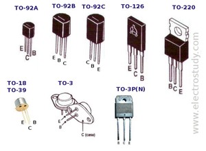
I hope i can get the two MJ's in a To126.
here is a link for ref parts list if any one needs *Keyboard Systems - Lowrey IC's and Transistor Listing*
cheers
A collation from the manual Jon linked.
Your pictures show discrete Darlingtons instead of the integrated Darlingtons in this plan; otherwise it looks a lot alike. Even the unexpected light-bulb as VAS protection(?).
> in a To126.
This is a 40+ Watt power amp; maybe 80 Watts in the Bass channel (if you have the many-channel configuration). The outputs HAVE to be TO3 or TO220 types to handle the power. (Or TO218, but that would be odd for 1982.) I have used TO126 outputs, but in a 20 Watt amp, not this big.
Attachments
hello,A collation from the manual Jon linked.
Your pictures show discrete Darlingtons instead of the integrated Darlingtons in this plan; otherwise it looks a lot alike. Even the unexpected light-bulb as VAS protection(?).
> in a To126.
This is a 40+ Watt power amp; maybe 80 Watts in the Bass channel (if you have the many-channel configuration). The outputs HAVE to be TO3 or TO220 types to handle the power. (Or TO218, but that would be odd for 1982.) I have used TO126 outputs, but in a 20 Watt amp, not this big.
I have found the exact service manual for my friends model. here is the link http://www.lowreyforum.com/manuals/L22_Fiesta_Part1.pdf
the organ is a 25watt powering a 12", the manual say 1980, though a sticker on board says 1982
i searched the parts (the three transistors) and the listing its gives me is the same parts as the other model the dx600 Jonsnell thought it might be, the mj1001 and mj901 I can only find these in the large oval T-03 type which wont fit with out drilling etc and im worried about grounding and shorting on the mounting plate if i do this.
my friends is definitly a L22 fiesta, cant understand why the parts are so different. i can measure the parts after work next week.
It has got me confused about what to order, if any one could let me know a the common or direct replacement parts numbers and package type, that would be a direct or similar replacement awesome. I'm happy to jump wires if the leg config is different, cheers
Last edited:
I have a power amp he can have, was going to try and keep close to original for him.If the power amps are FUBAR, an LM3886 or similar big chip-amp wired single-supply would probably work and be much more bullet-proof.
sorry did you ment the close up photo of my friend amp shows To-126? , I didnt look at types properly before posting, cheers
Last edited:
If the manual is correct then Q3 you have the big picture of, the most common npn-pnp pair in TO3p is ON semi mjl4281/4302.
Another common pair is fairchild FJL4215/4315
However outputs are shown as darlingtons. this is q4 & q5 in the manual. The most common ones in TO3P are TIP142/147. In TO220 the most common darlingtons are TIP102/107.
TO3p is the big pattern TO220 is smaller.
Equivalent to TO3p are TO247 & TO 264 the difference is too subtle for me to tell.
In AUS, check farnell.com sydney, use their selection table to see what they have in stock. Select transistors single, set package to click all the ones you are looking for, set wattage >100 Vce >80 see what they have in stock. they mix up darlington and regular transistors, you have to read the text to sort those out. You won't get counterfeits from them.
Warning on my DVM darlington transistors read open circuit. However I will get one scan of numbers on ohmsx2000 by contrast with a real open circuit.
Do change the insulators under the transistor & heat sink compound. Farnell sells a nice multicomp mica kit for TO3p another for TO220. Usually it shows up as "also bought" on the right when you have the individual transistors data page. They are hard to find otherwise.
Changing to TO3 oval should be totally unnecessary.
Last edited:
thats what has me puzzled , the photo of the 1980 L22 fiesta organ and specs for it are identical to my friends. maybe it was old stock and had a later 1982 amp fitted when it was built? there is a 1982 sticker on my friends amp.Um... that manual you linked shows outputs as Q5,Q6, but your board photo shows Q3. SO the manual does not seem to match your organ, though the circuit might be the same. That would explain why the parts list says TO3 transistors while the photo shows TO218.
Or there are several models that look alike. MAny home organs look similar.
A 1980 model could easily be made for quite a few years, certainly two years later is no stretch. Peavey Made Classic 30 amps for well over two decades before they updated the innards and continue to sell it to this day.
If you cannot identify the model you have, where did you find its specs?
A 1980 model could easily be made for quite a few years, certainly two years later is no stretch. Peavey Made Classic 30 amps for well over two decades before they updated the innards and continue to sell it to this day.
If you cannot identify the model you have, where did you find its specs?
The key to finding out whether your blown output transistors are darlington are not:
Are there TO220 (or TO5) drivers with heatsinks? Do the baselines from the output devicess come directly from a large heat capable transistor pair, or do the signals come from TO92 pea sized transistors. If the former, regular transistors. If the latter, darlingtons.
If the transistors over on the right of your picture are unconnected to the output transistors (and I think I see +22 near one) then the outputs are darlington TO3-p or TO247 transistors.
Last edited:
Page 24 of manual is amp schematic http://www.lowreyforum.com/manuals/L22_Fiesta_Part1.pdf first few pages has photo of model and specs, looks exactly the same and has same speaker etc. Page 38 has amp power transistors listings numbers under sub title 'chasis plate'.Or there are several models that look alike. MAny home organs look similar.
A 1980 model could easily be made for quite a few years, certainly two years later is no stretch. Peavey Made Classic 30 amps for well over two decades before they updated the innards and continue to sell it to this day.
If you cannot identify the model you have, where did you find its specs?
Referenced the 12 digit lowrey parts numbers to actual parts on this link. *Keyboard Systems - Lowrey IC's and Transistor Listing*
thanks
Thanks for all the help, I will see I can pick up the amp board from my friend after work and i will get a definite on weather the L22 schematic matches, hopefully it does,The key to finding out whether your blown output transistors are darlington are not:
Are there TO220 (or TO5) drivers with heatsinks? Do the baselines from the output devicess come directly from a large heat capable transistor pair, or do the signals come from TO92 pea sized transistors. If the former, regular transistors. If the latter, darlingtons.
If the transistors over on the right of your picture are unconnected to the output transistors (and I think I see +22 near one) then the outputs are darlington TO3-p or TO247 transistors.
if it doesnt I can overlay a transparent picture the underside circuit tracks over the topside components and will hopefully be able to give you some more information about the transistors connections to the power ones.
thanks again,
- Status
- This old topic is closed. If you want to reopen this topic, contact a moderator using the "Report Post" button.
- Home
- Live Sound
- Instruments and Amps
- need help with diagnosing organ power amp problem