unclejed613 said:uh, guys..... i hate to point this out........ look at the original post, and carefully at the drawing....... uh, EF output, with the PNP collector connected to the positive rail, and NPN collector connected to the negative rail........ doesn't that look a bit odd? that might explain why the magic blue smoke refuses to stay inside the transistors............
not just a bias problem, but it's a reverse bias problem.........
Look even closer, Uncle Jed.

The diagram shows 2 PNP transistors, but he mentioned he made a mistake in the drawing and the top one really is NPN. That sets things right again methinks.
..Todd
jaycee said:Good luck finding an opamp that will take more than about 18v supplies. If you have powered that up already, you have fried the opamp.
I have a seperate +-15v regulated power supply for that, running from a seperate transformer.
I also put a new set of transistors in and run the thing off the +-15v used for the opamps and it ran fine, not entirely sure about the sound quality, its good but there are previous active filters, to get rid of the high frequency as I am using it for a subwoofer.
What is a QSC, im kind of new to the fourms and don't all the lingo yet?
What is a QSC, im kind of new to the fourms and don't all the lingo yet?
i can sumurize this for u
if you want ....
if you dlike to make one diy amplifier to make kabboom kaboom for a sub woofer it would be much easier to skip the "design" issue and go for a construction of onechip amplifier LM3886or even stk ....or simply go for prooven design
messing up with this configuration will not do much as long as a few things are not properly designed .....
i can give you one example only that is enough to skip this design ....
in all amlifiers the bias drifts upwise as long as the amp is getting warm and pushed to the limits ...so in all amplifiers there are circuits to reduce bias ...or control it depending on the temperature amplifier ...
that is the reason one that this amplifier cannot opoerate in high power ..... it will suffer from thermal instability or thermal run away as we say ....
any other design even the most simple like a 3886 has all these features included ....
this will give the pleasure of construction and at the end of the day will work happily ....
there is nothing wrong to be a beginer at amplifiers all of as has been there ....
the only problem is that when you are a beginer you should take advice and determine your needs in a diferent way ..... power versus stability versus quality versus construction complication and so on and on and on ....
yeah I know what you mean, I really should have done that in the first place, but I think ive acquire sentimental value to try and get it to work correctly. Theres always going to be easier ways and ones which get the results quicker, but I'm going to keep trying when I have time making subtle improvements as I go along. In some ways its another way of learning what works, what doesn't and how all the individual section of the amplifier work together.
I'm going to buy a lower voltage transformer so that I don't keep blowing up the transistors.
In the physical design the diode would be glued with thermal cement to the transistor packages so that they heat along with the transistor to compensate for the thermal runaway and alter the bias. At the same time since the opamp follows the output it will also compensate for any shifting in bias. How good these compensations are I don't know.
my real annoyance is that I didn't want things to be too complicated and so I figured this design wasn't too complicated it had good sound quality and is quite efficient.
Ive learnt loads in the past 3 years on this project and my design has changed greatly, but ive learnt so much because of this.
furlow said:I think its my calculations, which were lazyly done using a piece of electronics modeling software. I should have done them my self as well.
Thanks to everyone for all your help
learn to use the features of the SPICE software that monitor device currents. you can run a 2N3904/3906 output pair at 100A idle current in SPICE and they will still work. if you use the software to tell you what the device currents are, you'll probably find that even the circuit simulated well, the collector currents were probably way too high...
hmmmm
you can run a 2N3904/3906 output pair at 100A idle current in SPICE and they will still work. if you use the software to tell you what the device is......
THAT IS AVERY NICE BOMB !!!
CAN U TELL US MORE ????
i had a lot of fet smoke so far may bipolar is a diferent story
ha ha ha ha !!!!
best regrads everyone !!! we have easter .... health and love for every one !!!!
unclejed613 said:just to have a look at it i ran a sim of your circuit. your output transistors start at 110mA idle current. that's high even for much larger output devices.
your problem as somone said earlier is overbiasing the output devices......
can you run it with 17v rails instead of 56v
thanks please reply
it would be neat if SPICE would do an animation of smoke and fire when you exceed the ratings of a transistor. only problem is, nobody would get any work done for the first month or so, they'd be designing circuits to see how much fire and smoke they could create...
just to prove the point, i bumped up the output stage rail voltage in my simulation of the OP's circuit to +/- 1000V, and the transistors just happily chugged along putting out a nice 20Vp-p sine wave...with an idle current of 5.6A
just to prove the point, i bumped up the output stage rail voltage in my simulation of the OP's circuit to +/- 1000V, and the transistors just happily chugged along putting out a nice 20Vp-p sine wave...with an idle current of 5.6A
furlow said:
can you run it with 17v rails instead of 56v
thanks please reply
Sure, but you won't get a whole lot of output out of it. You could just keep the whole thing running off +/-15 and be done with it - and you'd have a whopping 9 or 10 watts.
It does sound like you're overbiasing - as you increase Vcc the voltage drop on the 51 ohm resistors is too much. It really needs to be a pot so it can be adjusted.
furlow said:
What is a QSC, im kind of new to the fourms and don't all the lingo yet?
Not really lingo - QSC is a major brand mane. They make PA amps. Most of their older legacy products use a very simple circuit where the driver and output transistors are driven directy by an op-amp (sound familiar?). They just hook up the high voltage supply differently to get voltage gain in the output stage without having to add any components.
But in any case, you've got to fix the over-bias problem first.
Okay here is as follows thanks for all the suggestions, I will get a lower voltage transformer and I will sort out the biasing problem so that its not over biasing the transistors.
thanks so far. I wont be back for awhile because im back to school on monday from easter break and lots revision for as level exams so I wont be back until may in about 6 weeks.
thanks so far. I wont be back for awhile because im back to school on monday from easter break and lots revision for as level exams so I wont be back until may in about 6 weeks.
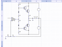
shown below is how a QSC type amp works. notice that the transistor collectors are grounded, and the power supply for the outputs has a center tap but it's not grounded. instead, the center tap and the power supply common float. the whole power supply is floated from ground. when positive-going audio is applied to the input the NPN begins conducting and pulls the negative rail towards ground, this in turn makes the positive rail and the center tap go more positive. negative going audio causes the opposite effect, making the PNP conduct and pulling the positive rail towards ground, and so the power supply and the center tap go negative. the speaker output is taken from the power supply center tap. i have shown the power transformer, bridge rectifier and caps in this drawing.
Attachments
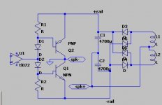
furlow said:Okay I built a push pull amplifier, there are other various filters before this part, but this is were the problem lies. The problem I get is a large current flowing through the two transistors, from 56+ to 56-.
I've done a design that's very similar to what you're showing here: Audio Strip. This being part of a longwave receiver. Even though it doesn't use a +/- supply, that doesn't really change anything. I never had any problems with poofing transistors here, since this design includes the emitter resistors to set the idle bias current. I would definitely include these.
I would also get that rail voltage down. While having some headroom is a good thing, +/-56V is overkill. If you need that much power, you're not gonna get it from an op-amp, as those don't operate at such high voltages, and the voltage swing just won't be there.
unclejed613 said:shown below is how a QSC type amp works. notice that the transistor collectors are grounded
Actually, it's the emitters that are supposed to be grounded. The trannies would connect just like in Furlow's original schematic - but the power supply is connected as in the QSC amp. The reason the QSC has grounded collectors is because they use unity-gain CFP's. Furlow was using prepackaged darlingtons.
The easiest way to wrap your head arond the concept is that the "ground" of the floating supply and the "speaker output" have their roles reversed. Simply physically swap the connections. To deal with the phase reversal, also swap the + and - inputs on the op amp. Note that this only works if the HV power supply is totally isolated from the op amps's supply - because no connection on it is ground anymore. But if I understand him correctly, that's what Furlow is doing anyway. Everything else in the QSC circuit has to do with filtering and overcurrent limit and doesn't absolutely have to be there.
- Status
- This old topic is closed. If you want to reopen this topic, contact a moderator using the "Report Post" button.
- Home
- Amplifiers
- Solid State
- Need help with a push pull amplifier problem