Identifying the relevant resistances will not be straightforward. For the cap between the first and second stage you have to consider the output impedance of the first stage and the input impedance of the second stage.
The first stage output impedance will be a bit less than 3.3k, because the resistor has the first BJT collector in parallel with it and there is negative feedback via the 1M resistor. The actual impedance here will depend to some extent on the impedance of the signal source. It all gets complicated, so I would assume 3k and not worry too much.
The input impedance of the second stage is set by its current (9mA?) and its current gain. Then in parallel with that there is the 120k resistor. Wild guess say around 5k.
Then there is the 1k series resistor so you get a total of 9k to combine with the 640nF cap.
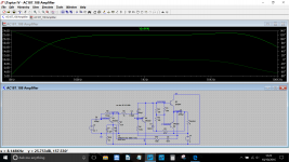
I didn't have 680nF caps, so I put 150nF for the first one and 470nF for the second one. Will test later today if it passes enough lower frequencies. I guess anything over 70hz would be good.
Here are those values.
Attachments
I don't have LTSpice and don't know how to use it. It's on my todo list, but never have time to do it  I even created software (DIYLC, you may have heard) for drawing layouts and schematic, just to avoid learning LTspice and similar. I find them very complicated
Can you please just try how it looks with 150nF input cap and 470nF for coupling? I promise I won't bug you anymore.
Cheers,
Bane
I even created software (DIYLC, you may have heard) for drawing layouts and schematic, just to avoid learning LTspice and similar. I find them very complicated Can you please just try how it looks with 150nF input cap and 470nF for coupling? I promise I won't bug you anymore.
Cheers,
Bane
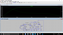
thank you, this is very helpful. I put the two plots on top of each other and stretched to match the scale. Looks like the roll-off starts around 300Hz in the second one and it's around 2db lower at 100Hz. I'll probably add some capacitance to flatten the response between 100Hz and 300Hz.
thanks again, I owe you a beer or whatever you like
thanks again, I owe you a beer or whatever you like
 and your very welcome
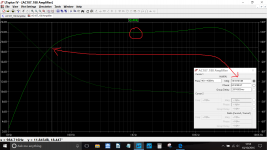
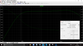
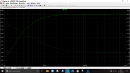
Yes. Although, some bass roll-off is desirable here, otherwise it may sound farty or boomy when it gets overdriven by strong guitar signal. I'll try it tonight with my guitar speaker. It also has roll-off around 100Hz (plot is below). If there's not enough bass, I'll just add another capacitor in parallel with the existing ones. Btw, my output capacitor is 470uF instead of 400uF, so it may compensate for some of the bass loss
Cheers
An externally hosted image should be here but it was not working when we last tested it.
Cheers
Last edited:
Reporting back, I tried two variations and I think there's slight difference in favor of higher capacitance and I stuck with 0.47uF in fist and 1uF in the second position. It sounds just awesome with my Strat guitar. Very clean and warm...and very similar to good tube amps. There's slight breakup when pushed hard, but it's very pleasant. And it's surprisingly loud. With my efficient guitar speaker it's much louder than the regular TV level. Even maybe too loud for apartment.
Thanks to both of you for your help.
Thanks to both of you for your help.

yes. The couple I checked are in the +10-20% range...but I won't do anything about it as it sounds really good
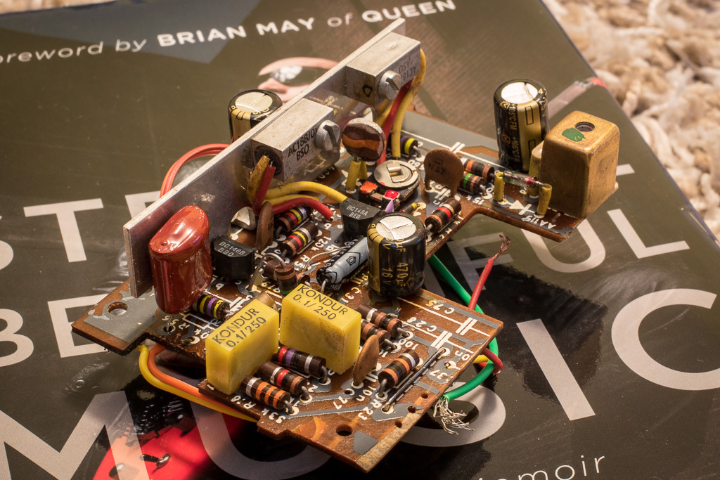
in some tube amps I've played with, the old carbon comp resistors look kind of dry and crumbly, but these look really good. I have some new production carbon comp resistors and they look about the same.
in some tube amps I've played with, the old carbon comp resistors look kind of dry and crumbly, but these look really good. I have some new production carbon comp resistors and they look about the same.
- Status
- This old topic is closed. If you want to reopen this topic, contact a moderator using the "Report Post" button.
- Home
- Amplifiers
- Solid State
- Need help understanding AC187/AC188 radio amp circuit