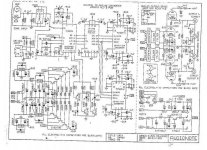
On the schematic I am using for this zener it clearly states it is 8v2 ( 8.2 volts, naturally )...but on the zener it says c3voph..which to me is 3.0 volts?.
It is an Audio note dac two ( circa 1997 ) ....the schematic I have is for a dac4...but The cct's look mostly identical to me ...
The schematic is floating around here somewhere...I will try and post it soon for all to have a look at.....the zener in question is just after the 7805 reg which supplies the digital board.
Thanks

hhhmmmm
Hi Karl....how u been...you helped me with another post a while back..it was a cal dac with a dc offset prob and no bleeder resistor, which u fixed.
Anyway, to the problem at hand...yes looks a bit odd...so does that mean you can confirm c3v0ph is an 8.2 volt zener, as that is what is marked on the zener and it came out of the cct marked 8v2 on the scematic????...if I measure from one side of the zener ( with it back in the dac ! ) to zero volts , should I get 8.2 volts??.
thanks

twists and turns!
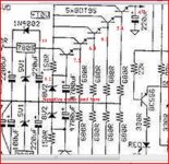
well, I understand what is going on now...where it is marked 8v2 on the schematic, in reality there were TWO zeners in series , not one as I had thought. They are 4v3 and 3v0 in series (so 7.3 volt in total )...so I replaced them with paralelled 7.5 volt zeners ( parallelled to lower the dynamic impedance ? ) and it is humming again.
thanks Karl
I'd have to think about that ! you have all those base emmiter junctions in series too all adding to the tempco problem.
Sounds like the diodes were producing noise, seen it happen, you get a burst of RF as they come into and out of conduction. Adding a small cap across the input to them often cures it. Good it's sorted.
Sounds like the diodes were producing noise, seen it happen, you get a burst of RF as they come into and out of conduction. Adding a small cap across the input to them often cures it. Good it's sorted.
- Status
- This old topic is closed. If you want to reopen this topic, contact a moderator using the "Report Post" button.
- Home
- Source & Line
- Digital Line Level
- Need help to indentify zener diode c3v0ph