Hey everyone. I am working nights this week and haven't been getting any sleep so my days have been spent in bed.....I haven't checked anything on the amp since I first posted my query. I am hoping to pull myself together here today and try testing all the voltages. I hate to work on these things powered up and half asleep if you know what I mean....can be a shocking experience.
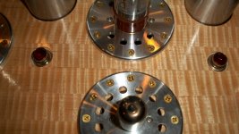
I did purchase the round disks from VT4C.com, I think they were about $6 each or something like that. S/H from that place is really high though.
The filament transformers are brand new, doubtful both would be bad. The problem is not one sided, it is both channels. I did realize one thing I did not do....the grid leak resistor, 330K to the 5687, it was ommitted. I used a 100K pot as a integrated setup. I was understanding that this could be done like this.....could this be the problem? Maybe I should add this in and see what happens.
Jeff
Pics
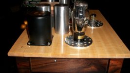
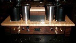
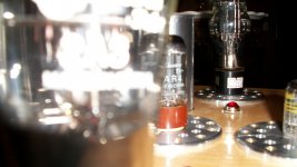
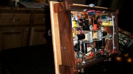
A few more pics for your viewing pleasure....
A few more pics for your viewing pleasure....
Attachments
-
 2A3 Hagtech Clarion Final 002.JPG545.8 KB · Views: 133
 -
 2A3 Hagtech Clarion Final 003.JPG599.8 KB · Views: 127
 -
 2A3 Hagtech Clarion Final 010.JPG448.9 KB · Views: 126
 -
 2A3 Hagtech Clarion Final 011.JPG339 KB · Views: 107
 -
 2A3 Hagtech Clarion Final 008.JPG492.2 KB · Views: 101
 -
 2A3 Hagtech Clarion Final 006.JPG559.6 KB · Views: 60
I don't thinks so because he is using a pot. This pot takes over the function of the grid leak resistor.I think you nailed it, the missing grid leak resistor is most probably what causes the problem!!
Yes, but what about the value of the difference between the 100K pot and the 330K grid leak resistor? Do you think this has any effect on the grid? I have lowered the effective value a whopping 200% from the designed specs. I think I will add back at least a 220K grid leak resistor, that would make up the difference.Oh, then I misread, thought he removed the pot ("I used a 100K pot" -- can indeed be interpreted either way).
I am about to put a voltmeter on the amp for the first time since I started this post. I actually got about 5hrs of sleep last night so I am feeling up to it. Given the problem I defined is there any particular place I should be looking to find the problem? I went back over the entire wiring of the amp and carefully traced out everything again. It appears to be wired correctly. I have star grounded the entire amp, the only ground points not directly grounded to the star are the (-) leads of both bypass caps, these are connected just under each resistor, on the ground side of the resistor, which is connected directly to the star. I have double checked the polarity of all capacitors, all of them are correct as well.
Given the only thing I did out of spec was the addition of a pot with a lower value than the grid leak resistor, I am wondering if this really may have something to do with it.
Jeff
Just thinking, if you get an increase in sound as you power down, something must be getting saturated. I wonder if you are over working some transformer core that isn't up to spec. I also suspect the power supply, since it is in both channels. Could there be a defective or miss-labeled choke? A bad PS transformer? Maybe measure the voltage output at various places in the PS circuit while powering down.
Unless, of course the grid leak issue resolves it.
Unless, of course the grid leak issue resolves it.
Just thinking, if you get an increase in sound as you power down, something must be getting saturated. I wonder if you are over working some transformer core that isn't up to spec. I also suspect the power supply, since it is in both channels. Could there be a defective or miss-labeled choke? A bad PS transformer? Maybe measure the voltage output at various places in the PS circuit while powering down.
Unless, of course the grid leak issue resolves it.
Everything is new and the transformer is the exact model Hagerman used for the design. The pre-tube measurements were acceptable too. I will have some numbers in the next couple of hours for everyone to digest.
Jeff
Given the only thing I did out of spec was the addition of a pot with a lower value than the grid leak resistor, I am wondering if this really may have something to do with it.
Not unless the pot was wired incorrectly, and your source is cap coupled. Do you measure 100k from the grid to common? A lower value resistance in that position will just lower the input impedance to the amp. An input impedance of 100k will be fine for any typical source.
Sheldon
This is still the first thing I would suggest you do.Quote:
I have not yet had the time to put a DDM on it with the tubes in it.
That is the first thing I would suggest you do.
This is still the first thing I would suggest you do.
I'd do that second. First, I'd set the schematic in front of me, and measure every point to point resistance. I find most of my mistakes that way. It won't catch a reversed electrolytic, but most other faults.
Sheldon
Even better.First, I'd set the schematic in front of m...
Hi Jeff,
I noticed from your photographs that you have used shielded cables from the plate circuit of the input tube to the grid of your 2A3. I have found in the past that the capacitance of this cable can cause the 2A3 to oscillate, i.e. it goes unstable. To overcome this problem, you need to position R9 in you schematic so that it is physically connected directly on the pin of the 2A3 socket, so the grid of the 2A3 see’s R9 before it sees the capacitance of the shielded cable.
Another point I noticed is that the input tube grid is DC coupled to the input connector, which can produce problems if your pre-amp has any DC voltage on its output that will effectively change the bias of the input tube. I suggest that you add a capacitor of say 0.1uF (a film type) in series with the input connector just to make sure that this does not happen. Hope this help.
Regards
Peter
Jeff, I don't think a lower grid leak resistor can make any difference.
Do you have a function generator, and a multimeter that can measure AC voltages up to, say, 1kHz (check the manual)? In that case, you could try to isolate the problem to either the input stage or the power stage.
Do you have a function generator, and a multimeter that can measure AC voltages up to, say, 1kHz (check the manual)? In that case, you could try to isolate the problem to either the input stage or the power stage.
Do you have a function generator, and a multimeter that can measure AC voltages up to, say, 1kHz (check the manual)? In that case, you could try to isolate the problem to either the input stage or the power stage.
If not, use your regular (non-RMS) AC voltmeter and use mains voltage as your signal source, stepped down to, say, 1V through appropriately sized transformer(s), of course. Non-RMS voltmeters are designed to give accurate readings at least at mains frequency.
If not, use your regular (non-RMS) AC voltmeter and use mains voltage as your signal source, stepped down to, say, 1V through appropriately sized transformer(s), of course. Non-RMS voltmeters are designed to give accurate readings at least at mains frequency.
I think anyone tackling these sorts of projects should at a minimum have a decent DMM that reads true RMS and can handle a couple of kHz or better. They aren't that expensive. A cheap function generator and a basic scope will take you a great deal further once you learn to use them.
eBay offers a tremendous amount of reasonably priced new and used test equipment for a lot less than the cost of many of these projects.
No real excuse IMO, just a matter of money and priorities.
Agreed.
I mentioned the alternative for those who don't happen to own or be able to afford such gear just yet (afterall even the crappiest 'scope will cost more than complete tube amplifier, transformers included, which might be too much for somebody only just venturing into DIY electronics).
I mentioned the alternative for those who don't happen to own or be able to afford such gear just yet (afterall even the crappiest 'scope will cost more than complete tube amplifier, transformers included, which might be too much for somebody only just venturing into DIY electronics).
...even the crappiest 'scope will cost more than complete tube amplifier, transformers included.
You'd be surprised what you can find on the 'bay. I think I paid $40 shipped for this 15 MHz scope. The switches are pretty scratchy, and sometimes you have to jiggle them a little to get the trace to come in clean. Still, I find it a useful tool. I just need a signal generator to go with it.
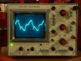
http://i69.photobucket.com/albums/i43/Ty_Bower/Oscilloscope/P1080401.jpg
Gear
I have a sad confession.....I own 2 oscilloscopes and 2 function generators and still have not taken the time to learn how to use them. Really I don't even know where to start. I do have a very nice DDM too that is up to the task.
Just woke up from a small nap, schematic in front of me, DDM in hand and the amp upside down on the kitchen table. As soon as I have given my wife some much needed attention (30min or so) I am going to get this thing done.
Thanks for reminding me about putting the resistor directly on the pin of the tube....I do remember reading about that somewhere. I will take care of that as well...an easy fix.
Jeff
- Status
- This old topic is closed. If you want to reopen this topic, contact a moderator using the "Report Post" button.
- Home
- Amplifiers
- Tubes / Valves
- Need help solving problem on new 2A3 build