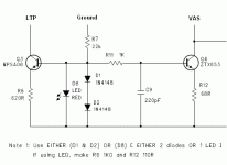
with a resistor loaded LTP the varying currents in the collectors sends the changed part of the current through the load as well as generating a voltage to drive thehigh impedance at the VAS input.
Replacing the resistive collector loads with an active load changes what the LTP is required to do.
The increased collector current cannot pass extra current through the active load. That active load has been designed to have a very high impedance (over the operating bandwidth).
All the changed current is expended in raising the voltage at the VAS input.
It is the change in effective collector load impedance that apparently changes the gain of the LTP+VAS stage.
This is mentioned (if not explained in detail) in D.Self, Leach, Cordell and others.
you don't need an active "mirror" to balance the emitter currents of the LTP pair.the schematic does not have a current mirror and it is very unbalanced. So, I want to replace the 2 resitors (R4,R5) with a current mirror to balance the LTP and gain some slew rate.
You achieve this "balance" by choosing the correct resistor values and currents around the LTP stage.
You can "gain" slew rate by changing the currents and the loads seen by the LTP.
Hello Andrew T and thank you.
Yes, it is mentioned by Self and Cordell that with the active mirror load, current is not wasted in the passive collector resistor.
I was trying to "balance" the LTP and gain some speed with one move, without changing gm, at the expense of a little noise from the degenerating resistors.
Regards,
Dimitrios
Good thinking! It's actually even better than that.I was trying to "balance" the LTP and gain some speed with one move, without changing gm, at the expense of a little noise from the degenerating resistors.
Regards,
Dimitrios
Firstly, you can forget about the noise contribution; it's insignificant. Aside from anything else, you've already got the noise from R3 (4.7K), so adding another 50 Ohms won't make any difference.
Replacing R4 with a mirror doubles the speed of the amp and balances the tail currents of the LTP to minimize distortion from the input stage.
It also means Q5 is driven from a high source impedance, which reduces distortion in the VAS.
As an added bonus, degenerating the LTP with emitter resistors increases it's linearity as well, resulting in much lower distortion from the input stage.
~~~~~~~~~~~~~~~~~~~~~~~~~~~~~~~~~~~~~~~~~~~~~
In the schematic you showed the LTP tail current is about 1mA total, or 0.5mA per transistor, so the emitter resistors should be about 56 Ohms each.
~~~~~~~~~~~~~~~~~~~~~~~~~~~~~~~~~~~~~~~~~~~~~
Edit: BTW, is this a Naim clone? The only time I remember seeing RC networks like that between the VAS and output stage was in a Naim amp schematic. Weird.

Attachments
Last edited:
Hello godfrey.
Thank you for your reply.
Yes, this is a Naim clone. They use base stopper resistors (?) of different values (?). Actually, I have not yet found how the value of base stopper resistor is determined. The RC networks I do not know what their function is. Maybe we can get an answer from other members.
Another weird thing is that they use this extremely unbalanced 1st stage LTP. Simulation shows that R4 passes 615μA and R5 passes 241μA.
Regards,
Dimitrios
Thank you for your reply.
Yes, this is a Naim clone. They use base stopper resistors (?) of different values (?). Actually, I have not yet found how the value of base stopper resistor is determined. The RC networks I do not know what their function is.
Another weird thing is that they use this extremely unbalanced 1st stage LTP. Simulation shows that R4 passes 615μA and R5 passes 241μA.
Regards,
Dimitrios
I remember remarking on this recently and some years previously.this is a Naim clone........................
Another weird thing is that they use this extremely unbalanced 1st stage LTP. Simulation shows that R4 passes 615μA and R5 passes 241μA.
It must be part of "their sound" creation.
Deliberately introduce non-linearities that sound "nice".
- Status
- This old topic is closed. If you want to reopen this topic, contact a moderator using the "Report Post" button.
- Home
- Amplifiers
- Solid State
- Need help please
