For EF86, the output is connected to one vol. control.
Are you sure the volume for the EF86 is connected to the power supply rail? I don't think the line in's are used for microphones since you already have a MIC input.
Here is an example of what NOT to do when you restore the amplifier - such a shame...
Last edited:
jazbo8
The volume control is connected at pin 6 of EL86 and then can be switched to pin 3 of ECC83. There is a pot to inject some DC voltage to source 1 and 2, maybe to elevate the input signal. That´s what I do not understand.
I want to make some modifications for safety reasons, but keep the monoblocks as closed as the original. What that guy did was taking identity of the original amplifier. I'm with you, this should not be done.
Very good, thank you a lot.
I will turn on one monoblock e measure the voltage and check with your values. They seem to be very close.
The feedback resistor is 33k (330k was wrong as the r22 that is 68 ohms/50w). But it was projected for 800 ohms at the output of OT. Now, which value should I use?
About the input of EF86, what kind of source can I connect? I tried a CD input with a passive preamp but the gain is too high. Is there any mod that I can do to get better results?
About diodes, I included them as suggested on post #3.
If the output is suposed to be 800 ohm then you get 240V~ there at 70W.In that case a feedback resistor of 330k is very possible.
To get the ~voltages I put in, the feedback resistor is 240k.
As I mentioned the inputs of the EF86 has a phantomsupply.That is the input carry a positive voltage (adjustable with the two trimpots),don't connect something whatever.Probably for mikes that consist of a capacitor changing with air pressure (sound vibrations),they need a voltage across them.
Since I wrote down the sensitivity on several points in the amp.choose an apropriate entrance to put a vol.control there.
Mona
Bingo! You seems to be very familiar with these units. Now, the EF86 circuit makes sense.
But this leave me another problem: the circuit is useless ....
Backing to main circuit, I will measure voltages and look for an appropriate OT to use. I think I'm going on the direction you already pointed.
Thank you again.
But this leave me another problem: the circuit is useless ....
Backing to main circuit, I will measure voltages and look for an appropriate OT to use. I think I'm going on the direction you already pointed.
Thank you again.
Last edited:
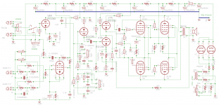
I re-drew the schematic in a more conventional manner, to make it a bit easier to follow. It looks like a pretty straight forward PA amplifier, if you want to convert it for hi-fi, you should bypass the tone controls and the input switching/phantom supply. You may not even need the EF86 if you are driving it with a CDP. Of course, as Ketje suggested, the feedback network needs to be changed to accomodate the new OPT, especially if you are going to wire the output tubes for UL operation. When all is done, you are going to end up with a pair of very cool vintage monoblocks, congrats!
You can down the schematic here.
You can down the schematic here.
Last edited:
jazbo8
The drawing is much better. Which software did you use? It 's much better to understand.
I will measure voltages tonight and post here to get your opinions.
Now, the amp is becoming more interesting to me, I can start to understanding how it works and how the stages are interconnected.
Thank you.
The drawing is much better. Which software did you use? It 's much better to understand.
I will measure voltages tonight and post here to get your opinions.
Now, the amp is becoming more interesting to me, I can start to understanding how it works and how the stages are interconnected.
Thank you.
jazbo8
The drawing is much better. Which software did you use? It 's much better to understand.
Glad you like it, this is the program that I use.
Glad you like it, this is the program that I use.
Downloaded. I found it very nice to draw schematic. Eagle is good to PCB, but not so good to draw only wire/components .... I will try to learn and use next time.
I"m guessing that the value of the cathode bypass caps on the middle two triodes sould be 47uf, not 0.47uf.
Which one? I didn't find 0.47uf capacitor. Do you the number of it?
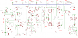
I"m guessing that the value of the cathode bypass caps on the middle two triodes sould be 47uf, not 0.47uf.
Now I see! On the new schematic. Thank you.
Forget the feedback loop. My signal generator was disconnected. Everything looks working good. Now, I'm waiting for components that I ordered. It will take more than 20 days!
Thanks I lot
Which OPT did you order, will it have UL connection? Are you planning on keeping the GZ34's?
I already ordered from tubedepot:
From mouser:
I was thinking about this OT:
https://www.edcorusa.com/cxpp100-ms-3_3k
It has good price, but I not sure about quality .... I saw good and no so good reviews about quality sound.
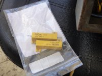
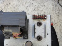
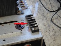
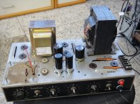
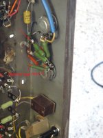
I'm thinking about remove 56/20w resistor and insert a choke in it's place. Is it a good idea? There is room inside chassis to do this.
The pictures show what I wish to do. Any advise?
- tube sockets
- wire (20 AWG 600v)
- coupling capacitor
From mouser:
- capacitor (all types)
- wire
- connectors
- other stuff to my all diy projects
I was thinking about this OT:
https://www.edcorusa.com/cxpp100-ms-3_3k
It has good price, but I not sure about quality .... I saw good and no so good reviews about quality sound.
I'm thinking about remove 56/20w resistor and insert a choke in it's place. Is it a good idea? There is room inside chassis to do this.
The pictures show what I wish to do. Any advise?
Attachments
Last edited:
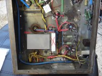
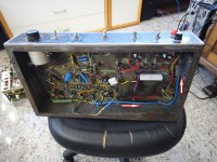
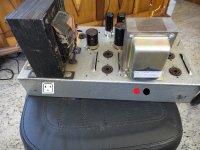
Now I'm working on the chassis, de-soldering components and removing all tube sockets and wires. I will keep one monoblock to guide me on reconstruction.
I want repaint inside chassis to remove oxide and clean everything.
For safety reasons, I'm thinking removing AC and the speaker connectors from top to back as show in the pictures. My heart is suffering with this ....
As the same type, I'm currently thinking about use EF86 as input, working like Mullard 5-20. The pots could be used as a pre-volume. I will try to draw a schematic, now using the new software and watch your advices.
The pictures shows what is going on!
Attachments
I was thinking about this OT:
https://www.edcorusa.com/cxpp100-ms-3_3k
It seems ok, but I think the blue end bells ruin the vintage look of the amplifier...
If you have the room and the budget, I don't see why not.I'm thinking about remove 56/20w resistor and insert a choke in it's place. Is it a good idea? There is room inside chassis to do this.
This is a good idea.For safety reasons, I'm thinking removing AC and the speaker connectors from top to back as show in the pictures. My heart is suffering with this ....
- Status
- This old topic is closed. If you want to reopen this topic, contact a moderator using the "Report Post" button.
- Home
- Amplifiers
- Tubes / Valves
- Need Help - Monoblock Power Amplifier EL 34