No, the 2N3055 can't handle the high voltage rails of the Phase 400. And even if it could it would introduce other problems. You need to get the amp stable with the transistors you intend to use. If the amp will run with the resistors in place of the fuses as outlined above, you shouldn't lose any more output transistors if you leave the light bulb in place and pull the plug if it goes bright.
If you have to order more output devices anyway from DigiKey you can just get the "fuse resistors" and compensation caps, etc. from them. I can also make some suggestions on good cheap DMM's if you want to mail order one. http://jameco.com has some bargains for example.
If you have to order more output devices anyway from DigiKey you can just get the "fuse resistors" and compensation caps, etc. from them. I can also make some suggestions on good cheap DMM's if you want to mail order one. http://jameco.com has some bargains for example.
Well, I just solved one mystery. It wasn't my multimeter acting up, it was the transistors! I had ordered 12 MJ21196's, but they sent me MJ11033's instead. Hopefully they'll take them back, although I probably already fried a couple of them. I guess in the mean time I'll concentrate on the oscillation in the left channel
I've been following this post and have been waiting to jump in with something. Though it's been a few years since my last PL400II repair, the oscillation problem reminded me of something. A friend had his PL repaired by another friend, all bad parts were replaced and still the thing oscillated. My turn now to repair this beast, all I did was to replace the Silpad transistor insulators with good old mica and grease and all was fine, still runs today, that was 15 years ago. So if you are using Silpads or similar, don't.
Craig
Craig
Yeah, the capacitance between the output devices and heatsink is part of the stability equation in some amps. And so is how the heatsink is grounded. Which brings up a good point: I'm not sure how the chassis of the 400-II is supposed to be grounded to the circuit, but given how modified Blue Lander's is, that's something to check into. Make sure the problem channel driver board and output transistor wiring match the working channel--especially the ground wiring.
I've also seen some spectacular case-to-heat sink shorts from using silpads. If there's any "flash" (sharp edges) on the transistor mounting surface or the heatsink holes, silpads more easily lets the sharp edges compromise the insulator. And the result is the full power supply gets dumped into the resulting tiny short. On a large amp with large filter caps you can end up with some melted metal and damage to the heatsink mounting surface. Mica with grease is way better.
Sorry about the wrong transistors. If they've been soldered in place, I doubt DigiKey will take them back. But it's worth asking.
Before you spend a bunch of money on new transistors, I want to suggest once more considering the LME49810 driver board solution. You'd still have a 90% authentic vintage amp but one that sounds better and is (hopefully) much less likely to fry your tweeters and itself. The amp would look the same, still have the cool meters, same power output, etc.
If you go that route, you probably want a fully complimentary (PNP/NPN) output stage so that would change what transistors you buy. I'd probably vote for the NJL4281D/NJL4302D which should make the bias situation easier and they are also well tested (with impressive results) with Panson's driver board.
But, being realistic, the new driver board may present its own challenges in adapting it to the 400-II. And I also realize you already have (hopefully) one good working channel. But if I were in your shoes I'd go the LME49810/NJL3281 route in a second.
Also, as I said, the Large Advent tweeters are famously fragile due to a small voice coil, no ferrofluid cooling, and a really low crossover frequency sending much of the midrange to the tweeter. So if the Phase Linear has even some brief bursts of oscillation playign music (say due to instability at clipping or when current limiting) the tweeters are almost certainly toast. Plus, stacked Advents are a 4 ohm load and many amps are less stable into low impedance loads--especially at clipping or because the current limiting (SOA protection) triggers instability. The Baker Clamp circuit in the LME49810 is designed to prevent instability at clipping and reduce clipping distortion--things that may well save your tweeters. Just my two cents worth...
A couple of things that may (or may not) have been overlooked. First, the feedback loop *will* close with the outputs removed. 150 ohms Rbe on the drivers, 10 ohms on the outputs. The predrivers must remain in the circuit. Second, if you get high current (light bulb on) with the outputs in place, and they check out ok, remove *all* bias by shorting out the Vbe multiplier. It's that little small signal transistor routed from the PCB to the heatsink. Another common failure mechanism for these amps is an open Vbe multiplier. The transistor itself is mechanically fragile. I replace mine with BD139's usings fine standed wire for the connections and lots of heat shrink. Also, check the PNP predriver while you're at it. Third, the bulb *will* go dim if everything is working. There will be a huge DC transient on the output terminals and possible oscillations, but it will work. Once the AC mains get over about 80VAC it will stabilize.
About the DC300A - it uses roughly the same topology as the PL400 S2! It has a few minor refinements which help its overload behavior. The CE1000 and 2000 were basically the same thing as well (but were cheap junk by the usual Crown standards). The topology is also a VERY favorite of bass guitar amp makers.
If you wanted to DIY your own amp in that chassis, you certainly couldn't be faulted. A true complementary output stage is nice and easy to do. You could even use the original driver baords with a bit of rework. And adding baker clamps, replacing those super-hot shunt regs with a series pass transistor, and a more modern op-amp in the front end are all very viable upgrades.
Watts abundant apparently makes a output relay protection board (mentioned here: http://www.audiokarma.org/forums/showthread.php?t=194898) but it goes for 90 bucks. I'm changing the values of one of the caps in the crossover network to send more midrange to the woofer as most Advent experts suggest and I'll also put a fuse on both sets of speakers. It looks like a LME49810 costs only 5 dollars. How much in additional parts would I have to buy other than transistors?
If I went the fully complimentary route, could I use some of the MJ11033 PNP's I already have, assuming Digikey doesn't take them back?
If I went the fully complimentary route, could I use some of the MJ11033 PNP's I already have, assuming Digikey doesn't take them back?
11033's? I don't think so. They're only good to 120V - and even if you do find some that can take more, they have no useable SOA above 30V. And you can't just plop in darlingtons.
The only PNPs you should be considering are MJ15023/5 or MJ21193/5. I know everyone will suggest using some high fT flatpacks, but that's a lot of extra chassis rework and may not even work right the first time. With three current gain stages and the extra open loop gain of the op amp it's just a lot of unnecesary grief for little if any return.
A DC muting relay is always a good idea with these amps. The rail fuses are supposed to handle this, but 5 amp fuses are right on that fuzzy border between nuisance blowing and being ineffective if the amp does fail.
wg_ski said:
About the DC300A - it uses roughly the same topology as the PL400 S2! It has a few minor refinements which help its overload behavior. The CE1000 and 2000 were basically the same thing as well (but were cheap junk by the usual Crown standards). The topology is also a VERY favorite of bass guitar amp makers.
Interesting. It's getting off topic, but does the Crown DC300 use an op-amp in place of the usual diff. pair? If you're talking about the VAS and quasi-comp output stages, that wouldn't surprise me. But using an op-amp in place of a discrete input stage just seems to create more problems than it solves so I'd be surprised if Crown did it?
The DC300 has a reputation for being one of the more bulletproof amps in its day. Another was McIntosh. Their amps could be used as arc welders without complaint due to their output transformers and costly overkill design. And the Dynaco 400 was more robust than the PL400. The Phase Linear and Mac amps looked expensive and many had cool metering which helped their popularity. Of course the Mac amps *were* expensive. The other popular big amps of the era were the SAE/Ampzilla models but they blew up even more then Phase Linears did.
Fortunately, not too much later, the Hafler DH-200/220 and DH-500 came along and were cheap, very robust and sounded better than anything above. You could also arc weld with those. I know a dealer that wired around all the fuse holders and would run a DH-200 at full output into a short loop of small gauge wire (basically a dead short) until the wire glowed dull red. The bimetal thermal switch on the heatsink would finally shut the amp down if he let it run like that for very long. Those Hitachi lateral MOSFETs are impressively tough and quite a novelty when they came out.
So, back on topic, another avenue might be to pick up a Hafler DH-200 for the Large Advents if the 400-II turns into a money pit. The Hafler is within a few years of being the right vintage, and with new electrolytic caps, will probably easily work perfectly for another 30 years.
")
RocketScientist said:
Interesting. It's getting off topic, but does the Crown DC300 use an op-amp in place of the usual diff. pair? If you're talking about the VAS and quasi-comp output stages, that wouldn't surprise me. But using an op-amp in place of a discrete input stage just seems to create more problems than it solves so I'd be surprised if Crown did it?
Crown continued to use the op amp input stage all the way up through the MA-5002VZ. Of course these amps were symmetrical, had local feedback, Baker clamps, and analog computers to calculate junction temp. The op-amp front end wasn't what made the PLs fragile or unstable.
Originally posted by wg_ski Another common failure mechanism for these amps is an open Vbe multiplier. The transistor itself is mechanically fragile. I replace mine with BD139's usings fine standed wire for the connections and lots of heat shrink. Also, check the PNP predriver while you're at it.
I think I'll replace both those transistors since they're cheap enough. Also, the channel only started oscillating when I set the bias down to zero. Before I did that, the variable resistor was set to about .5k and the channel behaved as normal.
blue lander said:
I think I'll replace both those transistors since they're cheap enough. Also, the channel only started oscillating when I set the bias down to zero. Before I did that, the variable resistor was set to about .5k and the channel behaved as normal.
Yeah, some amps don't like their bias at zero as it essentially opens the feedback loop at low signal levels depending on the driver/bias configuration. Zero bias can cause the DC operating point to move until a driver or output transistor turns on which closes the loop, corrects the offset, and the cycle repeats resulting in oscillation. So I'm not sure about wg_ski's advice to short out the bias to zero? The procedure I gave earlier to set it by measuring the current in the driver emitter resistors should work well.
And thanks for the answer wg_ski. That's interesting. I agree Bob Carver's designs may have well been unstable for other reasons--especially given some of his all discrete designs were also marginally stable. One has to wonder if he really understood the math/measurement behind proper compensation back then or he was just forced to compromise due to his marketing claims of wideband "linear phase" and keeping the cost down? But, regardless, the higher open loop gain and potential additional poles with an op-amp being in the loop could make stability compensation more difficult.
And yeah, the Crown "analog computer" was one of their more impressive claims to fame. Like the old McIntosh amps, the high cost of some of the Crown amps was at least partly justified by all the extra engineering and circuitry that went into them.
Another side comment: Thanks again for the Crown info wg_ski. I just downloaded the service manual and schematics for the DC300A and the Macro Tech 5000VZ and Crown has done some interesting stuff.
I wonder, being now owned by Harman International, if all their design work is still done in Indiana or if some of the cheap stuff is ODM/OEM from offshore or otherwise re-badged non-Crown gear? With a 400 watt Crown XLS 202 priced at $300 you have to wonder? If it's all still 100% US designed (like say Mackie) that would be very cool. But I suspect Harman might be leveraging the brand like they've done with everything else they bought (i.e. Mark Levinson, etc.).
I wonder, being now owned by Harman International, if all their design work is still done in Indiana or if some of the cheap stuff is ODM/OEM from offshore or otherwise re-badged non-Crown gear? With a 400 watt Crown XLS 202 priced at $300 you have to wonder? If it's all still 100% US designed (like say Mackie) that would be very cool. But I suspect Harman might be leveraging the brand like they've done with everything else they bought (i.e. Mark Levinson, etc.).
RocketScientist said:
Yeah, some amps don't like their bias at zero as it essentially opens the feedback loop at low signal levels depending on the driver/bias configuration. Zero bias can cause the DC operating point to move until a driver or output transistor turns on which closes the loop, corrects the offset, and the cycle repeats resulting in oscillation. So I'm not sure about wg_ski's advice to short out the bias to zero? The procedure I gave earlier to set it by measuring the current in the driver emitter resistors should work well.
Are you sure the bias wasn't accidentally set all the way up rather than down? Just shorting between the two prediver bases usually works well as a diagnostic tool, with no load. It's supposed to be a quick way of checking whether a high draw is due to an open (or mis-adjusted) Vbe multiplier or shorted driver/output.
RocketScientist said:I wonder, being now owned by Harman International, if all their design work is still done in Indiana or if some of the cheap stuff is ODM/OEM from offshore or otherwise re-badged non-Crown gear? With a 400 watt Crown XLS 202 priced at $300 you have to wonder? If it's all still 100% US designed (like say Mackie) that would be very cool. But I suspect Harman might be leveraging the brand like they've done with everything else they bought (i.e. Mark Levinson, etc.).
Everyone makes cheap amps nowadays. It's all part of the price war and most of it is made in China, even if US designed. You can still get good Crown amps - they just don't have 'XLS' on them, and you do have to pay for them. Same goes for everybody else's amps - you can buy a cheap Crest or QSC and be disappointed, too. Or you can buy their touring models and have something every bit as solid as the old DC300A at ten times the power.
wg_ski said:
Are you sure the bias wasn't accidentally set all the way up rather than down?
Yup, I checked it with a multimeter. It's not zero ohms exactly but it's low as it'll go.
RocketScientist said:
The procedure I gave earlier to set it by measuring the current in the driver emitter resistors should work well.
I'm going to try that tonight. Ideally I should use something running off battery like an unplugged laptop?
wg_ski said:
Everyone makes cheap amps nowadays. It's all part of the price war and most of it is made in China, even if US designed. You can still get good Crown amps - they just don't have 'XLS' on them, and you do have to pay for them. Same goes for everybody else's amps - you can buy a cheap Crest or QSC and be disappointed, too. Or you can buy their touring models and have something every bit as solid as the old DC300A at ten times the power.
Yeah, I was speaking more just as a fellow engineer. I'm not in the market for any fan cooled pro amps. But from an engineering perspective I hate to see a legendary 50+ year brand name slapped onto marginally engineered bargain products designed by someone else. I understand the desire to have competitive offerings at all price points, but at what point do you sell your soul in doing so? BMW, for example, doesn't even try to compete with entry level cars. Even their Mini starts around $20,000. That's also true for lots of other high-end companies and brands. Some companies choose to leave the cheap stuff to someone else.
Even Steve Jobs recently said "we don't know how to make a computer for under $500 that is not a piece of junk". Of course, with netbook sales through the roof, and Apple having nothing to offer, he might now regret that statement.
blue lander said:
Yup, I checked it with a multimeter. It's not zero ohms exactly but it's low as it'll go.
I'm going to try that tonight. Ideally I should use something running off battery like an unplugged laptop?
First you should set the bias in the drivers with nothing connected to the inputs. Then, before hooking up any output transistors, it would be good to verify on the scope the driver board seems to be working correctly by playing some music (or even better a .WAV or MP3 file of a sine wave) on the scope.
And yeah, whenever the scope is connected to the amp, it's safest to not having anything grounded connected to the inputs (like a desktop PC or any audio gear with ties somewhere back to ground like a cable TV connection to a TV connected to a receiver etc.). So the safest is stand alone gear. It should be fine to run the laptop from AC as long as it has only a 2 prong AC adapter. A portable MP3 or CD player also works well and is very safe.
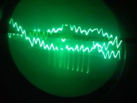
Wow, I'm suprised by the results. The oscillating channel stopped oscillating with even a little bit of bias, I guess it just doesn't like running with no bias. I connected my laptop (running off battery, not connected to the mains) to the PL400 and started playing music off of Youtube. The LEDs in the front of the unit for both channels start jumping around, but the left channel (the formerly oscillating one) was jumping quite a bit more than the right channel (the one I thought was good.)
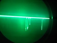
The first picture I've attached is what I saw with the scope connected to the left channel. It looks like "music" except for those weird negative spikes. They seem to be intermittent and random. The right channel, however, was mostly flat with just a few fluctations. When I get home, I'm going to check all the components I put in the right channel, it's possible Digikey sent me additional wrong parts....
The first picture I've attached is what I saw with the scope connected to the left channel. It looks like "music" except for those weird negative spikes. They seem to be intermittent and random. The right channel, however, was mostly flat with just a few fluctations. When I get home, I'm going to check all the components I put in the right channel, it's possible Digikey sent me additional wrong parts....
Attachments
- Status
- This old topic is closed. If you want to reopen this topic, contact a moderator using the "Report Post" button.
- Home
- Amplifiers
- Solid State
- Need help fixing an odd Phase Linear 400