Hello everyone!
I had this idea for a while, but only now had time to come up with a rough draft of the schematics.
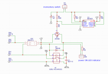
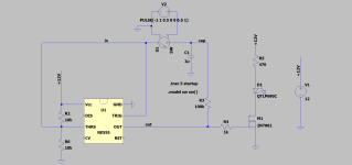
Board has a simple functionality that will allow the user to power on/off various devices by a simple push of the button.
When the device is on, LED is lit to indicate operation.
1W SMPS is used to energize the NE555 circuit that monitors the user input.
When the user pushes the button, relay connects mains live.
When the user pushes the button second time, relay disconnects main live and LED is turned off.
Mains neutral is passed through at all times.
Please feel free to point out any obvious flaws.
Appreciate everyone's help!
I had this idea for a while, but only now had time to come up with a rough draft of the schematics.
Board has a simple functionality that will allow the user to power on/off various devices by a simple push of the button.
When the device is on, LED is lit to indicate operation.
1W SMPS is used to energize the NE555 circuit that monitors the user input.
When the user pushes the button, relay connects mains live.
When the user pushes the button second time, relay disconnects main live and LED is turned off.
Mains neutral is passed through at all times.
Please feel free to point out any obvious flaws.
Appreciate everyone's help!
Attachments

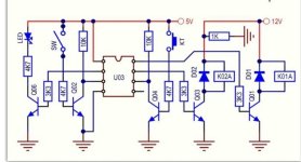
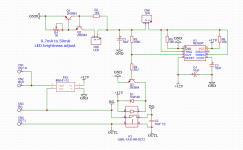
What you want to do can be done with 2 transitions, a few Rs and one C... see below. Enjoy... I used it in y amp builds for fancy customers... It requires a constant 12V supply, though.
For 5V DC Vcc, scale down the 15K resistors proportionally.... try 5k resistors.

For 5V DC Vcc, scale down the 15K resistors proportionally.... try 5k resistors.
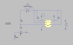
This can work but:
1. You did not set the switch input threshold to a positive voltage, so it defaults to zero, so it never turns off driven only to zero volts.
2. It is a bad idea and confusing to name ground = -12V. "-12V" implies a negative voltage, not zero Volts.
3. Using the fet as a follower is a bad idea because the gate threshold is significant so the output will be reduced. Especially bad if you power with 5V.
Attachments
500 ohms will do fineG5RL-1A-E-HR-DC12 relay is 360ohms so will other resistor should be 360ohms as well?
Reminds me of RAM cell of some sort, thank you!
Any NPN with 800mW dissipation (to be on the safe side with 12V / 360ohm coil)... like BC635, 637, 639... or their equivalentsWill 2N3904 be a better transistor to replace the one that drives the relay?
Edit: I just checked the 2N3904... yes, it will work fine as well...
Some ideas pertaining to the subject, having various functions including toggle:
https://schematicsforfree.com/files...sc/IC Provides Versatile Toggle Functions.pdf

https://schematicsforfree.com/files...sc/IC Provides Versatile Toggle Functions.pdf
There are mechanical push-push switches that would do the same thing, and then you would not need the electronics or the small supply constantly drawing wall current, albeit a minimal amount. Some of those switches have a built-in mechanical indicator or an indicator lamp that shows the state of the switch if button position does not give that away. I'd go that route if for no other reason than that reliability is higher the fewer parts you need to implement a function of some sort. I'd go electronic with the switch if I wanted to have it work with a remote control. The added complexity would make sense then.Hello everyone!
I had this idea for a while, but only now had time to come up with a rough draft of the schematics.
Board has a simple functionality that will allow the user to power on/off various devices by a simple push of the button.
When the device is on, LED is lit to indicate operation.
1W SMPS is used to energize the NE555 circuit that monitors the user input.
When the user pushes the button, relay connects mains live.
When the user pushes the button second time, relay disconnects main live and LED is turned off.
Mains neutral is passed through at all times.
Please feel free to point out any obvious flaws.
Appreciate everyone's help!
Yeah, that is the idea actually - to keep adding more functionality to it.
Possible additions will be 12v trigger input, speaker protection input, two color LED switch to indicate STBY and ON, LED brightness adjustment, etc...
I plan on using this with my amplifier and I really like anti-vandal push button switch by E-Switch on Mouser PV6FW40SS-331.
Possible additions will be 12v trigger input, speaker protection input, two color LED switch to indicate STBY and ON, LED brightness adjustment, etc...
I plan on using this with my amplifier and I really like anti-vandal push button switch by E-Switch on Mouser PV6FW40SS-331.
Thank you everyone for so many different suggestions and ideas!
I think I will go with the NE555 based schematics by ESP - https://sound-au.com/project166.htm
Hopefully in the future will try two transistor filp flop version as well.
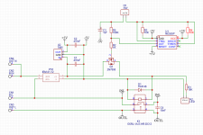
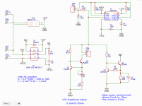
The latest revision is same what ESP has with the addition of LED brightness adjust using constant current sink.
I am not sure about the value for R4 resistor. It is 2K2 now, but I changed transistor from BC549 to 2N3904 and kept resistance the same. I guess it depends on what is the voltage on the pin 3 OUT of NE555 and current needed for 2N3904 base?
Another question will be about D1 diode across the relay coil - is the polarity correct?
I think I will go with the NE555 based schematics by ESP - https://sound-au.com/project166.htm
Hopefully in the future will try two transistor filp flop version as well.
The latest revision is same what ESP has with the addition of LED brightness adjust using constant current sink.
I am not sure about the value for R4 resistor. It is 2K2 now, but I changed transistor from BC549 to 2N3904 and kept resistance the same. I guess it depends on what is the voltage on the pin 3 OUT of NE555 and current needed for 2N3904 base?
Another question will be about D1 diode across the relay coil - is the polarity correct?
Attachments
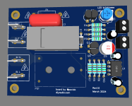
Just checked everything and there was a mistake - I connected LED circuitry to a wrong place.
Fixed it and also added power saving option for the relay - now instead of full 33mA, it should consume approximately 15mA.
15mA relay, 10mA NE555, and 10mA LED should result in total current consumed of 35mA.
Power saving CCS actually puts out full current of 33mA for about 10 to 15 mS to latch the relay. Only after it reduces the current to 15mA.
LED brightness adjust pot now has limiting resistor of 22R to prevent LED from damage due to current more than 30mA.
Relay coil now employs 1N4007 type of diode that is overkill but why not...
Fun stuff!
Attachments
Last edited:
- Home
- Amplifiers
- Power Supplies
- Need help designing push button mains switch based on NE555, Meanwell SMPS, and relay