Deleted caps are not replaced with anything. Just open circuit. There would be no input to R31. If you configure the circuit as I described, then the constant current source (CCS) causes V10 and V11 to function as an accurate phase splitter with gain. You could use a current regulator diode such as E-822 for the CCS, but there are many ways to implement this function. However, Edcor's CXPP50-3.4K has no cathode feedback winding, so I think this whole concept is invalidated. The original bass channel OPT probably will work as a wideband device, but that's no help if you want a twin-channel stereo amp. I believe this page shows the arrangement Eli recommended, and I also think it makes an excellent starting point: http://www.r-type.org/articles/art-003d.htm
Last edited:
I have once more changed the schematic, not completely according to your suggestions, but... Lets give it a try.
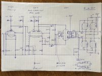
As first stage I propose a 6sj7 voltage amp
Second stage a anode cathode load phase plitter made of a 6sn7
Third stage 6sn7 driver with gain control poti
Forth stage 2 pair of 6v6
The 3rd and 4rth stage are equal to the original treble stage of the original Hammond cirquit.
I would like to split the signal up for the two parallel stages after the 6sj7 voltage amp in stage 1, and go from there to to parallel phase splitter-driver-6v6 stages.
Do I need the voltage amp in stage 1, or do i generate way too much gain for the following phase splitter and the rest of the amp?
I know... I did not follow all proposals from your sides, but nevertheless it would be great to have a feedback on my new approach.
Best regards, Thomas
Attachments
Thomas,
Your latest iteration would be interesting, if the I/P signal level was only a few milli-volts (mV.). A standard CDP produces a 2 V. signal. You have WAY too much gain.
Stop trying to exploit all of the tubes in your possession. Put away those not now needed for another project. Use Mullard style topology (3 stages), with a 6SJ7 voltage amplifier, 6SN7 LTP phase splitter, and PPP 6V6 "finals. The EICO HF87 is a good model. You change from a 12AX7 section as voltage amplifier to a 6SJ7. You use PPP "finals", instead of PP.
If you want to get "fancy", stack 0D3 and 0B3 gas discharge regulator tubes to make the O/P tube screen grid supply very stable. Regulated g2 B+ yields the best open loop linearity, when full pentode mode "finals" are employed, as is the case for this project.
Your latest iteration would be interesting, if the I/P signal level was only a few milli-volts (mV.). A standard CDP produces a 2 V. signal. You have WAY too much gain.
Stop trying to exploit all of the tubes in your possession. Put away those not now needed for another project. Use Mullard style topology (3 stages), with a 6SJ7 voltage amplifier, 6SN7 LTP phase splitter, and PPP 6V6 "finals. The EICO HF87 is a good model.
You change from a 12AX7 section as voltage amplifier to a 6SJ7. You use PPP "finals", instead of PP.If you want to get "fancy", stack 0D3 and 0B3 gas discharge regulator tubes to make the O/P tube screen grid supply very stable. Regulated g2 B+ yields the best open loop linearity, when full pentode mode "finals" are employed, as is the case for this project.
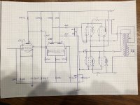
Better?
Getting close. Look at the HF87, carefully. Notice that the LTP is DC (not cap.) coupled to the voltage amplifier and that the non-inverting triode's grid is AC grounded via a capacitor. Those facts define Mullard style circuitry. Important characteristics of Mullard style circuitry include: low frequency stability and working well with O/P transformers of so/so quality. Those characteristics are exactly what this project needs.
Hi Eli
I am a bit confused, maybe I just do not see the obvious...
I have checked the drawing, removed the c between vamp and lpt, the non inverting grid is grounded, as far as I can say...
Could you please...
You were a great help up to now, I see that you want me to think about what I am doing and drawing.
I understood that gain is not about having as much as possible, but the right amount.
Its also not about using the whole bunch of tubes, but the right ones.
Thanks a lot for all the help.
Best regards, Thomas
Attachments
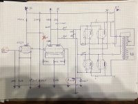
There are two standard ways to bias an LTP phase splitter. Your circuit seems to incorporate elements of both, and so will not work. I ask again, are you just copying bits of circuits or trying to understand them?
At present this thread feels a bit like a genetic algorithm at work: swap bits of circuit around randomly until the fitness function (i.e. us) says that the result is good enough. Computers may design things that way, but that is because they possess no 'deep knowledge'. People should be able to do better than that.
At present this thread feels a bit like a genetic algorithm at work: swap bits of circuit around randomly until the fitness function (i.e. us) says that the result is good enough. Computers may design things that way, but that is because they possess no 'deep knowledge'. People should be able to do better than that.
Dear DF96
I am trying to understand the cirquits... But it is quite difficult to understand them.
Google for 6sn7 lpt phase splitter, you do get no result that is congruent to the next one. There are many informations around, they all look different to me. Most examples do not work the said tube, whick makes it not easier to understand the whole. It might also be, that falso drawings corrupt the information available on the net (like my drawing).
So, please show me these two examples of lpts, that are proven to be correct concepts, and i will probably be able to find the mistakes in my drawing.
This would be more helpfull than just pointing out that there is a mix up in the cirquit, without a concrete hint where to look at.
Best regards, Thomas
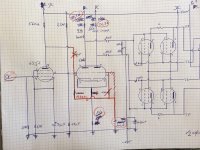
Yes, that looks better. It now looks like a classic Mullard DC-coupled LTP. I assume there should be a resistor where you marked 1Meg on the connection between the grids?
Have you visited Merlin Blencowe's Valve Wizard site? Or, even better, bought his book? You won't gain understanding just by looking at lots of circuits; that stage comes later once you have grasped the basics.
Have you visited Merlin Blencowe's Valve Wizard site? Or, even better, bought his book? You won't gain understanding just by looking at lots of circuits; that stage comes later once you have grasped the basics.
Yes, i have visited valve wizards site, and many others... Valve Wizards site is a great source of info.
I agree, i still work on the basics, just couldn'twait to get started.
Yes, it is a 1Meg resistor, you're right.
Thanks a lot once again, i will keep you up dated on the project.
I have just removed the trafo and the henries from one of the two amps, as soon as all parts have arrived i will start working - when I find the time to do it.
If there is room for improvement in the cirquit eg. the resistors or caps, I am open for feedbacks.
Thomas
Dear all
yesterday the tubes for the original Hammond HR-40 / LRA amplifiers have arrived..
As you can imagine, i wanted to hear how they sound prior to the conversion.
I have connected the output signal of the pre-amplifier to the two input signal lines of the LRA, and the output ground to the chassis.
Then I turned the tube amp on, gave it time to heat up and switched on the pre-amp, listening to classic rock radio.
And... nothing happened.
This was at gain 2 of 20 of the pre-amp. Then I turned up and up, to 20 finally, and very little sound was coming from the speakers.
Frustrating. I started measuring the output signal of the pre-amp; gain 2: around 0.1-0.2 Volt AC, gain 20: around 2.5 to peak 3.3 Volt AC, depending on the song.
I did this measurement several times, always with the same result.
A gain of 20 would blow the windows out with my solid state yamaha mx-70 amplifier.
It seems that the output signal is way under the said 10V from the specs of the pre-amp (if these are correct at all...).
I do not want to ruin my pre-amp by running it full load all the time.
What shall I do? I have not yet started building, just have the plans and some of the materials around.
Should I replace the 6SJ7 voltage am stage with a 6SQ7 tube, wired according to the general electric 6SQ7 datasheet (eg. http://www.mif.pg.gda.pl/homepages/frank/sheets/093/6/6SQ7.pdf), without the caps to be on AC voltage? This would give me probably a 50fold gain at 300V Ebb, compared to the max. 10-15fold gain of the 6SJ7. This means I would go to the 6SN7 phase splitter with approx. 2V, which is obviously still too low.
Or do I add another pre-step, prior to the amplifier shown on the last schematic; add a 6SQ7 resistance coupled amplifier with an Ebb of 300V (wired according to the general electric schematic, no caps), which would probably give a gain of 50fold, 0.2V*50=10V. And then go with these 10V to the 6SJ7 voltage amps in the schematic, with no additional changes.
Or do I just replace the 6SJ7 voltage amp with a 6SQ7 voltage amp and the 6SN7 tube in the phase splitter with a 6SL7 tube, which would probably give some additional gain (in a voltage amp up to 50fold).
Eli, can you also give me some advice here? This question goes much further than what I have read and (partly understood) by now.
Thanks for your comment.
Thomas
Last edited:
Preamps do not mind large signals, within their specification.thomasweissbach said:I do not want to ruin my pre-amp by running it full load all the time.
What exactly did you do? We need more detail. If the amp is balanced input, and the preamp is unbalanced out put, then you need to connect one of the amp inputs to the preamp output and the other to ground. If you put the same signal on both inputs then you get no output; that is supposed to be what happens.I have connected the output signal of the pre-amplifier to the two input signal lines of the LRA, and the output ground to the chassis.
well; I can't say if the preamp has balanced output; the specification does not say so (it's a parasound p/fet 900).
You might be right, that full power / output does not damage the preamp; nevertheless, the results was nearly zero that could be heard from the speakers (8ohm speakers).
The hammond amplifier has two + signal in pins on its sockets (pin 1 and 6) and a ground in, one + signal goes to the treble section, and the other one to the bass section (schematic is on first page of this thread). The hammond organ had also 2 signal out and a ground out for the tone cabinets.
I directly connected the output signal of the preamp to these two + signal wires on pin 1 and 6, and connected the ground of the preamp to the chassis.
Maybe I was not clear enough above; i soldered these two cables from signal + treble and signal + bass together and connected them with the output signal + of the preamp; and I connected the ground from the hammond socket, which is supposed to take the signal ground from the hammond organ, to the ground of the preamp output.
What should the approximate voltage of the preamp signal be for a tube amplifier prior to entering the voltage amplifiers and the phase splitter? I have not yet found any information about that.
I mean, if I only supply 0.1-0.5V with the preamplifier; will this ever become enough with the existing schematic, or the one I developed with your help?
Normal domestic power amplifiers typically need somewhere between 0.2V and 2V for full output. Generally the older the amp the smaller the signal it needs. Special-purpose amplifiers may need more or less than this.
The circuit given in post 10 has differential input on pins 1 and 6, so you should not connect the same signal to both. I assume the Hammond organ uses a differential output. Both signals go to both sections of the amp, as both bass and treble sections start with a differential amplifier (after separate crossover first order filters). So you either need a balanced output from your preamp, or you need to ground one input (pin 1 or 6) and put an unbalanced signal on the other input (pin 6 or 1).
The circuit given in post 10 has differential input on pins 1 and 6, so you should not connect the same signal to both. I assume the Hammond organ uses a differential output. Both signals go to both sections of the amp, as both bass and treble sections start with a differential amplifier (after separate crossover first order filters). So you either need a balanced output from your preamp, or you need to ground one input (pin 1 or 6) and put an unbalanced signal on the other input (pin 6 or 1).
Thanks a lot for your reply, it worked. I have placed 2 220 ohm resistors in series between the two signal inputs, palced the preamp signal output on one side to one of the amp inputs and ground connected the part between the to resistors. Both preamp sections work. Quite a good sound, rock radio, quality comparable to the solid state, but a bit poor in the voices (must come from the non hifi output amplifier). But not as loud as the solid state at the same gain level.
Lets build the new amp...
Lets build the new amp...
- Status
- This old topic is closed. If you want to reopen this topic, contact a moderator using the "Report Post" button.
- Home
- Amplifiers
- Tubes / Valves
- Need expertise for my first project, 6SN7-6SJ7-6V6