Ok this is my first layout design. So i would appreciate some input on this board. Its a mic pre using the INA217 and DRV134 for balanced out. It has phantom power, so it can be used for condensor or dynamic mics. the OPA134 is a DC output control loop.
I've etched a board and have done some listening. I've tested a SuperLux CH8, AudioTechnica 2020, oktava MK-219, and for dynamic i tested an SM7.
The SM7 really shined the best out of all the mics which surprised me but then again it is the most expensive of them. the AT2020 was the hottest of them. I dont know if the way i have the gain is set up has anything to do with it.
anyways any ideas? how would i implement a -10 or -20dB pad?
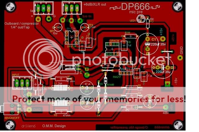
impsick said:Ok this is my first layout design.
Its a mic pre using the INA217 and DRV134 for balanced out.
It has phantom power, so it can be used for condensor or dynamic mics.
the OPA134 is a DC output control loop.
I've etched a board and have done some listening.
I've tested a SuperLux CH8, AudioTechnica 2020, oktava MK-219, and for dynamic i tested an SM7.
The SM7 really shined the best out of all the mics which surprised me but then again it is the most expensive of them. the AT2020 was the hottest of them.
I dont know if the way i have the gain is set up has anything to do with it.
anyways any ideas?
how would i implement a -10 or -20dB pad?
.
very nice 'your 1st layout' work, impsick
you use high quality IC: INA217, DRV134
in balanced configuration
this + very good 'pro' microphones, should make result be nothing but top class
at least if you can come very close to best possible values for supporting components ( resistors, gains, power supply etc. )
/Regards, lineup
Re: Re: need critique, Mic pre amp
thankslineup said:
very nice 'your 1st layout' work, impsick
you use high quality IC: INA217, DRV134
in balanced configuration
this + very good 'pro' microphones, should make result be nothing but top class
at least if you can come very close to best possible values for supporting components ( resistors, gains, power supply etc. )
/Regards, lineup
impsick said:
Anyone know how to
put a -10 or -20dB pad on the input?
I found a website a while ago but now i cant find it.
.
impsick
our forgotten audio friend
1. How is it going - project status?
2. Generally, to make -10dB / -20dB, is no big problem. Attenuate a signal.
... can be done in a number of ways - all of them good
3. It is when providing gain, +10dB / +20dB etc., we should take care.
... and those op-amps you use in your setup will ensure very good quality
Regards
lineup
")
DRV134 Audio Balanced Line Drivers Burr Brown Texas
Yes, darkfenriz, Good observation!
Looks like some bug / error.
Such big caps from output pin to GND will kill the signal, close to 100%
My guess they are suppose to be output coupling caps for the balanced XLR out,
and so instead should be put in series with the signal
= from output pins to output pads, jack.
Value of 10uF makes very good sense for this.
I know this about Those two 10uF:
They are NOT intended to be supply bypass caps for DRV134, V+ V-.
Because two such 1uF are already added at V+ V- (pins 5 & 6).
This is perfectly good as recommended ( 2x1uF ) in Texas datasheet:
Burr Brown DRV134, Audio Balanced Line Drivers
http://focus.ti.com/lit/ds/symlink/drv134.pdf
Regards
lineup
darkfenriz said:What are 10uF caps near output intended to do?
Yes, darkfenriz, Good observation!
Looks like some bug / error.
Such big caps from output pin to GND will kill the signal, close to 100%
My guess they are suppose to be output coupling caps for the balanced XLR out,
and so instead should be put in series with the signal
= from output pins to output pads, jack.
Value of 10uF makes very good sense for this.
I know this about Those two 10uF:
They are NOT intended to be supply bypass caps for DRV134, V+ V-.
Because two such 1uF are already added at V+ V- (pins 5 & 6).
This is perfectly good as recommended ( 2x1uF ) in Texas datasheet:
Burr Brown DRV134, Audio Balanced Line Drivers
http://focus.ti.com/lit/ds/symlink/drv134.pdf
Regards
lineup
the 10uf caps on the out are called for in the drv134 data sheet. I actually just used some Wima 6.8uf caps and my results have been good. The data sheet says to use the 10uf BP caps to minimize Vocm. it states that they dont affect the performance. I just wanted to play it safe, but i also included the option to have an unbalanced output which would bypass the drv134.
The mic pre came out very good. I still havent made a 10-20db pad yet, i've been side tracked. But it needs one, some mics are hotter then others.
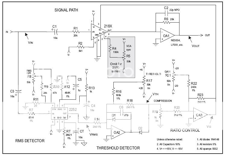
Ive been working on this compressor design if someone woould like to check it over. I havent been able to test it yet cause i burnt out my THAT2252 rms detector but i should be getting another one today or tomorrow.
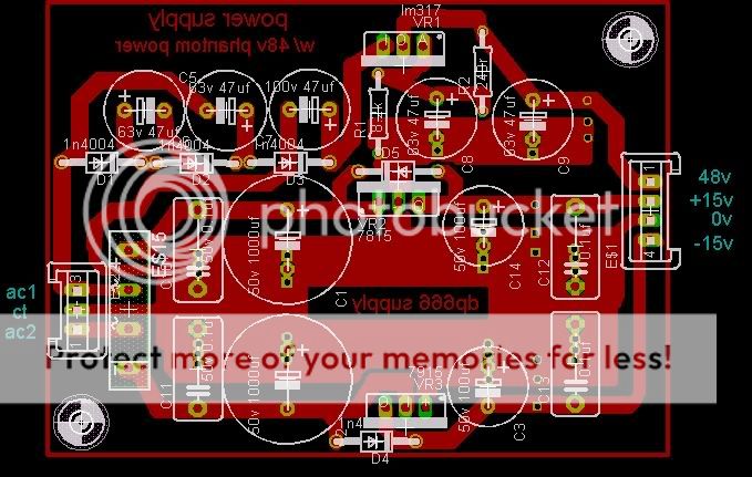
Here it is. and the power supply that is currently powering the mic pre and will be used to power both.

YOU ARE TOTALLY RIGHT ABOUT THOSE CAPS!!!! Thank you, very much for catching that guys. They should be ran in series, not to ground. It still works to ground haha. Anything visible in my compressor layout? Thanks again.
The mic pre came out very good. I still havent made a 10-20db pad yet, i've been side tracked. But it needs one, some mics are hotter then others.
Ive been working on this compressor design if someone woould like to check it over. I havent been able to test it yet cause i burnt out my THAT2252 rms detector but i should be getting another one today or tomorrow.
Here it is. and the power supply that is currently powering the mic pre and will be used to power both.
YOU ARE TOTALLY RIGHT ABOUT THOSE CAPS!!!! Thank you, very much for catching that guys. They should be ran in series, not to ground. It still works to ground haha. Anything visible in my compressor layout? Thanks again.
impsick
Good nice artwork
Thanks for publishing your layout and schematics
almost anybody can come a long way
in making such nice web presentation
Just by getting some nice freeware Schematic Drawing Tool and layout editor.
And some reading and looking at recommended circuit in Datasheets.
Make small adjustments to circuits, to match you own needs.
Maybe somebody else would like to build 'your project' .....
and maybe suggest some small clever changes.
We still need some good idea, where and how to put -10dB -20dB.
Have you considered to put this attenuation somewhere close to output?
Maybe BEFORE last output buffer IC ...
Regards
lineup
In the phantom supply section LM317 is on potential danger of burning, because when output caps are discharched and voltage trippler (right?) charges quickly, then input to output voltage can exceed maximum ratings, 35V or so...
You can add a protection zener diode to ensure the differential voltage on LM317 in-out is low enough, say 28V.
You can add a protection zener diode to ensure the differential voltage on LM317 in-out is low enough, say 28V.
thanks man, i appreciate the compliments.
As far as the attenuation at the output... What i've been noticing is that the 10-20dB pads are by the input. To control those fast/loud transients before its amplified.
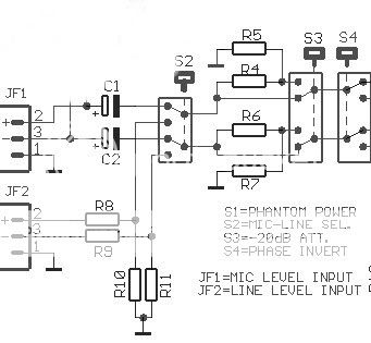
here is a schematic i found. this looks like it'll work. I'll work on the layout and post the result.
As far as the attenuation at the output... What i've been noticing is that the 10-20dB pads are by the input. To control those fast/loud transients before its amplified.
here is a schematic i found. this looks like it'll work. I'll work on the layout and post the result.
darkfenriz said:In the phantom supply section LM317 is on potential danger of burning, because when output caps are discharched and voltage trippler (right?) charges quickly, then input to output voltage can exceed maximum ratings, 35V or so...
You can add a protection zener diode to ensure the differential voltage on LM317 in-out is low enough, say 28V.
so a diode from the output voltage to the input voltage. Like a 1n4750? will that do?
i havent had any problems with it yet. No heat or anything but i'll take you advise and do things the safe way. thanks
darkfenriz said:
Also
it would be nice to mess something around 2252 to manipulate with time constants of attack/release of compressor.
what do you mean? it sounds very interesting but my knowlege of electronics isnt too advanced. Are you meaning like cap sizes?
Look here:
http://www.thatcorp.com/datashts/2252data.pdf
Under 'Time constants' they suggest that attack/release time can be altered by RT. If you wish you can use a pot in this place.
Pity is that you cannot separately adjust attack and release this way.
http://www.thatcorp.com/datashts/2252data.pdf
Under 'Time constants' they suggest that attack/release time can be altered by RT. If you wish you can use a pot in this place.
Pity is that you cannot separately adjust attack and release this way.
oh ok i get you now. i'll check that out. sounds kinda cool for an even simpler design. i like the idea of seperate control over attack and release, but this sounds interesting. i'll read up on it. sounds like something Presonus may have done on there Comp16. Just has a input pot, output, and a preset pot. i dont know if they used the 2252 or not but i do know that they used the THAT4301 in there Ureka channel strip, so chances they used the 2252 seem likely.
thanks.
thanks.
- Status
- This old topic is closed. If you want to reopen this topic, contact a moderator using the "Report Post" button.
- Home
- Amplifiers
- Solid State
- need critique, Mic pre amp