Hi TheGimp,
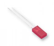
The image I used is a fair representation of the leds I have in my goody box. If it's not a fair representation of what's in other peoples goody boxes then it follows that my advice is of limited value.
I do tend to buy leds made by Kingbright from farnell which might make my goody box unrepresentative. ( I like cheap stuff )
)
Brgds Bill
The image I used is a fair representation of the leds I have in my goody box. If it's not a fair representation of what's in other peoples goody boxes then it follows that my advice is of limited value.
I do tend to buy leds made by Kingbright from farnell which might make my goody box unrepresentative. ( I like cheap stuff
)Brgds Bill
Attachments
Last edited:
As far as I know Kingbright are or were an offshoot of HP. So not cheap at all, in fact the reliable OEM version
I have some proper old school LEDs here. I guess they must be around 1971/2. Forget the normal 5mm case these babys have gold leads and a ceramic case (much like some early AN/USM and the JAN series transistors not to mention the extensive CV series) and a little clear epoxy top.
I prefer valves but there is growing interest in such things as germanium transistors etc. I have a load of old chips in lead frame packages that at this moment are worth nothing (appart from their extremely good performance). We forget this crap still flies planes about.
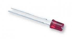
 but what makes you think you can tell from the pic which lead is which
 I have to agree that the photo looks like the longer lead goes to the larger flag.
This photo is from Farnell, I don't have this led to check it's polarity.
It only takes one manufacturer to do things differently and always suddenly becomes sometimes
Brgds Bill
This photo is from Farnell, I don't have this led to check it's polarity.
blow the theory that the larger flag inside the LED is always the negative
It only takes one manufacturer to do things differently and always suddenly becomes sometimes
Brgds Bill
I need bias voltage of 2.2 - 2.5v so according to the threads I should pick a green LED...
I need between 11-13 mA of bias current.
You have solved your own problem; just choose a LED that gives approx. 2.5 V at 10 mA! They all have datasheets, so check the forward I / V graphs. If you find two that do the same job choose the one with the lowest resistance.
Sounds like an echo chamber
I finally had time to put the LED bias in on one side. Compared to the other side which has the tradition cap/resistor it sounds like thin and like an echo chamber.
I'm getting bias voltage. 2.1 compared to 2.4 on the tube with the R/C network but that shouldn't account for that.
Anyone experience this?
I just thought that was a function of the LED having a fixed voltage. There's only three connections since I'm only using half the tube and going straight out with a OT. Pin 1 OT B+ Pin 2 Grid (pot) Pin 3 LED -- other channel r/c
Well, remember, the plate voltage is a strong function of the cathode-to-grid potential. That's how a triode amplifies. With a constant load (i.e., if you don't change the plate resistor), you've essentially applied a 0.3V signal, so the plate voltage should diminish by the amplification times 0.3.
Well, remember, the plate voltage is a strong function of the cathode-to-grid potential. That's how a triode amplifies. With a constant load (i.e., if you don't change the plate resistor), you've essentially applied a 0.3V signal, so the plate voltage should diminish by the amplification times 0.3.
Another reason to use a Plate CCS with LED, I find there is a real synergy with this combo.
No question, it's an excellent combination. But you'll have the same deal- if you change cathode-to-grid voltage, you should see a change in plate voltage. In fact, with a CCS load, the plate voltage shift should maximize because the stage gain will now be about equal to mu.
So in any event, if there's no plate voltage change with change in bias, then there's a problem somewhere.
So in any event, if there's no plate voltage change with change in bias, then there's a problem somewhere.
I'll look into all of it. There's no plate resistor just the OT. Plates are 192.7 on the other tube and 192.5 on this tube with the LED. As mentioned there's only three connections.
Could be the cheap LED although others mentioned cheap was good. I did get the next strongest up and I could try those. I thought about adding the cap back in but I thought the point of the LED was to be able to eliminate the cap.
Could be the cheap LED although others mentioned cheap was good. I did get the next strongest up and I could try those. I thought about adding the cap back in but I thought the point of the LED was to be able to eliminate the cap.
There's no plate resistor just the OT.
Aha, that clears things up- the OT is fairly much a short at DC. I'd check wiring and possibly replace the LED (I assume it's lit up!).
- Status
- This old topic is closed. If you want to reopen this topic, contact a moderator using the "Report Post" button.
- Home
- Amplifiers
- Tubes / Valves
- Need confirmation on LED bias for circuit