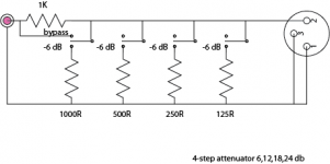
Then there's another method... having a series of shunt resistors that each add 6 dB ... of attenuation. The only caveat is that they have to be turned ON in sequence "conceptually left to right"...
R0 (first series resistor) = 1000 ohms
R1 (first shunt resistor) = 1000 ohms
R2 (second shunt resis.) = 500 ohms
R3 (third shunt resistor) = 250 ohms
R4 (fourth shunt resist.) = 125 ohms
So, with no resistors shunted ... you get the 1K series resistor and the 10K load impedance resulting in an innocuous -0.8 dB drop... almost nothing. Then as each of the resistors is shunted in in turn, additional attenuation, in 6 dB steps.
Kind of what you're looking for?
GoatGuy
- Status
- This old topic is closed. If you want to reopen this topic, contact a moderator using the "Report Post" button.