Help me, I'm stuck inside a DIY forum ....
Help for ... uh .. the challenged DIY audiot...
Help for ... uh .. the challenged DIY audiot...
An externally hosted image should be here but it was not working when we last tested it.
Nice pics, hollowman, and I can do my own macro-photos too, but... if somebody already knows where the pins are, then it could prevent a mishap.
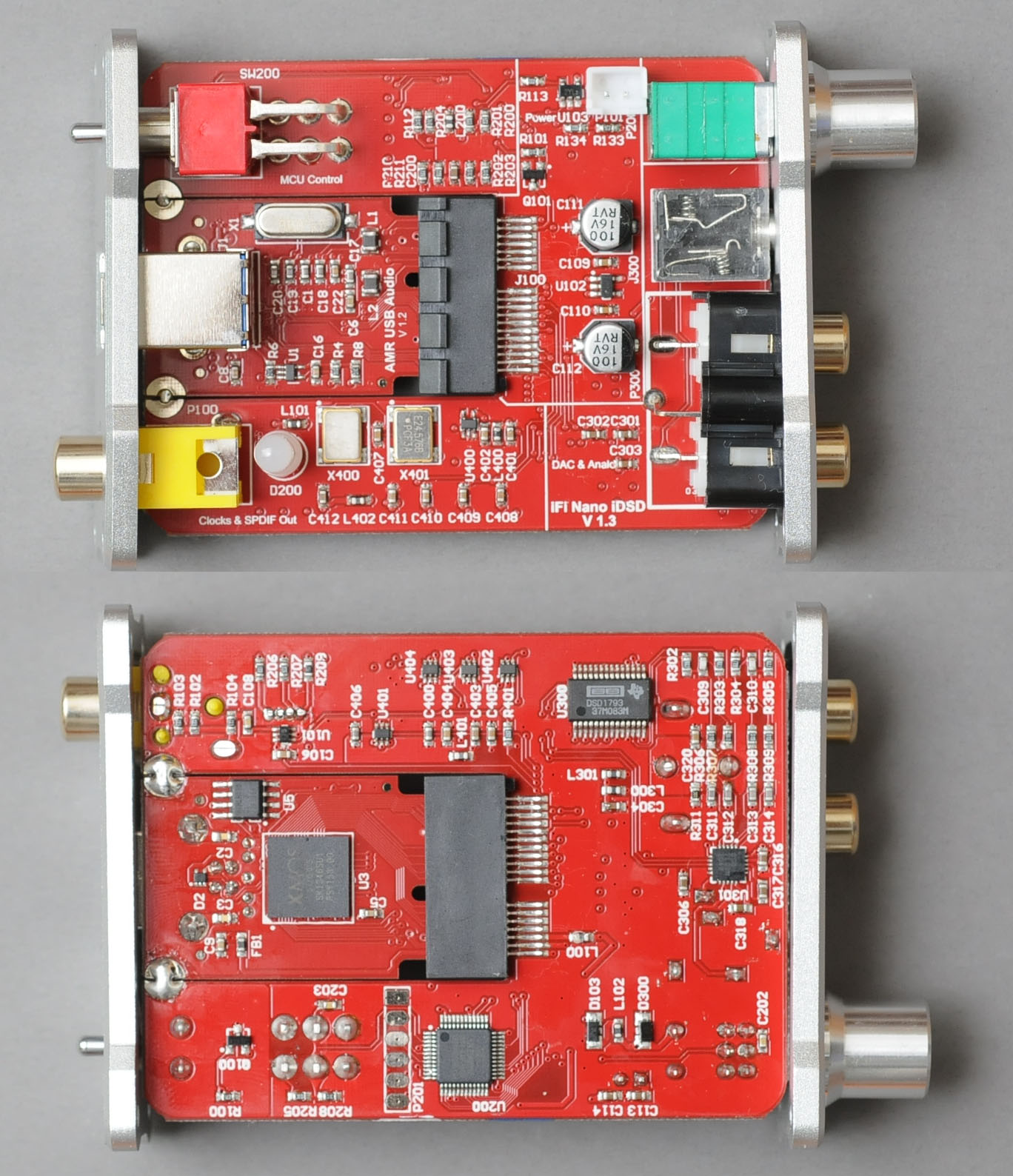
See that large multi-pin thing right in the centre? Do you think those closer to the DAC chip are the ones to look at? If I remember correctly, the DSD pins on the chip are among the first few ones.
See that large multi-pin thing right in the centre? Do you think those closer to the DAC chip are the ones to look at? If I remember correctly, the DSD pins on the chip are among the first few ones.
mterbekke: obviously because I want to tap the pure DSD output on these pins and not have to use DoP or go through a DSD DAC chip 😉
YashN,
DoP means DSD over PCM. That doesn't mean that it isn't dsd. It's just to get dsd out of a pc, over a usb connection that it is wrapped in a pcm format. Your XMos "unwraps " this and gets it back in its original DSD format. DSD or SDM means the same here. It is never converted by means of any sample rate or bitdepth conversion.
The advantage that native dsd has is that it has the potential to support much higher dsd datarates. That's basically all.
Regarding the pins:
In your dac, look for the DSD1793 chip : you need pins 24&25 for the original dsd right DSDR and dsd left DSDL data.
Clock SCK is on pin 5.
Goodluck!
Last edited:
mterbekke, you don't get it: I'm never said DoP isn't DSD. What I'm looking for is the pure DSD signal because I don't want to have to decode DoP to get to the DSD within.
So your explanation is good and true, but unnecessary to me. I do already listen to DoP (up to DSD128 only) on my Mac (can't do otherwise on Mac unless a driver becomes available) and already do higher than DoP rates using native DSD streaming with XP + Foobar2000 + a few plugins (I listen to DSD256 this way).
Thanks a lot for the pins info. I believe I will have to manually check if I can get the pure native DSD signal out of the XMOS chip.
The pins are tiny, so I'm afraid of shorting something and busting things.
Cheers!
On second reading, you're saying I will get pure DSD from the XMOS in any case, so it might be less hassle than I thought.
Will keep you posted if I get to tinker with it!
😎
Will keep you posted if I get to tinker with it!
😎
YashN,
There is no DoP signal there. Never. You can't look for one as it is only in the usb datastream.
So, you don't have to look for other dsd-like signals as there aren't any.
Xmos supports dsd and it has those dsd signals (never within a pcm wrap!) on its output pins. If you can't measure/recognoze these signals by means of an oscilloscope or logic analyzer, you won't be able to follow the dsd signals from the dac back to the xmos.
DoP rates: these aren't limited to 64 fs, most of the times they do as the dsd 64 signal is wrapped in 176.4 KHz and not many usb to i2s converters do 352.8 and higher. The ones that do and also support DoP, can do dsd128. You can find others that do it differently, but they might not support other standard pcm datarates, like 88.2
I don't see how this would not be absolutely necessary to you. It makes looking for a dsd signal easier, as it is everywhere on the board, you can't find dop on the board and there's no mix of pcm and dsd signals.
Your pure DSD signal is the only thing there.
Cheers!
Yeah, got you about the DSD signal - makes it a lot simpler than I thought.
But there's more to just higher rate with the native DSD: the fact that I don't want to use DoP means that I can access the native DSD256 streaming.
In turn, this means the XMOS won't need to deal with the overhead of decoding DoP, and hence less RFI/EMI around the signal.
Now, this is going to be fun because from the DSD256, I'll be able to experiment with a few things I have been thinking of on and off since I started the thread, but it had got to the back-burner while building my SET tube amp.
In other words, DoP isn't even in the picture with what I want to do, and basically, the limitations under Mac OS X are annoying.
I've asked iFi if they would use the exaSound technology to allow native DSD streaming on Mac OS X but they aren't interested in using someone else's technology.
That's a shame, but from what i read it's Apple's own mistake they gor pulled from Asio. And Core Audio(the main cause?) is probably here to stay for a while..
Totally following you on the EMI-thingy.
Wouldn't know what the best place is to tap in the dsd signal. I'm guessing at the dac inputs has got a few advantages:
-All is clear about the physical connections&datastream
-Which are way bigger than on the Xmos ;-)
Are you still on the serial to parallel conversion track?
Either way:
Someone before mentioned that you have to make the dsd signal return to zero. Otherwise you get distortions (still fairly enjoyable most of the times though) 🙂
Looks like you're almost done ;-)
G'night
Last edited:
Yep, I believe Apple made yet another change to CoreAudio or its insistence on PCM as supported format that somehow annoyed Steinberg enough to make the latter drop their personal support for ASIO on Mac OS X.
But exaSound did re-work one ASIO for Mac, and simultaneously made CoreAudioDSD256.
So to me, I will just have to be content with native DSD streaming and Win or Linux to get the DSD256 rate (or else get stuck with DoP128 max).
Still don't know how I was confused about DoP and the XMOS despite having read about the XMOS on their app note... a good thing you pointed this out to me, mterbekke, so, sorry I didn't believe in you!
I was thinking of tapping the signals at the XMOS itself, or secondly, at that large central slot with the pins sticking out (it's perhaps there for monitoring or debug). I have assumed here that the DSD signals are repeated there, but this is just conjecture.
I guess I could also tap at the DAC chip input, but I think this would be less than ideal as the signal goes further along the board to the chip.
Yes, you're correct about the Zero representations as in DSD, there are some specific codes for it.
As for serial to parallel, it looks like the best way to do it is just get an affordable FTDI interface, and maybe couple that with a small FPGA or CLPD as a couple of people have done.
The cost would probably be something less than $70 (FTDI) + $50 (FPGA) + $20 additional cost for analogue components for a total of $140 max. Not bad at all considering the results you could get.
Take Miska's HQ Player on main server computer to send it up-converted DSD256 and you're up and dancing.
Additional step: make an Ethernet input to the device, benefit from additional isolation, and then use HQ Player in client-server mode with Miska's Network Audio Daemon (but then the device would need to run a fuller O.S.).
When I get a breather from coding, I think I'll try finding those signals.
What makes you think I'll need an oscilloscope for finding the signal? 😛
Take care!
Another one who already did a cool project about this is member Koon!:
http://www.diyaudio.com/forums/digital-source/200818-dsd-playback-system-dsf-player-usb-ddc-dsd-amplifier.html
http://www.diyaudio.com/forums/digital-source/200818-dsd-playback-system-dsf-player-usb-ddc-dsd-amplifier.html
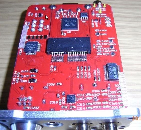
DSD Pins Test points
Check this out, I think I managed to find the test points for the DSD signals that go to the DAC chip on the XMOS board. See the pic below with the XMOS square chip and then the large rectangular connector with the two sets of pins, one smaller and one with many more? That's where we can get the DSD L and Right.
Now, we're only concerned with the larger set of connectors, but from the other side.
So, if you turn this board over and look at the rectangular connector with all the pins pointing to your LEFT, I believe that:
DSD L is Pin 2 counting from the top (of the set with the greater number of pins which should be above the other one).
DSD R is Pin 5 counting from the bottom of that set (NB we're unconcerned with the smaller set of pins here).
Now, all that remains to be done is solder wires to these (difficult) and then connect a low-pass filter to each of those and amplify.
Xmos supports dsd and it has those dsd signals (never within a pcm wrap!) on its output pins. If you can't measure/recognoze these signals by means of an oscilloscope or logic analyzer, you won't be able to follow the dsd signals from the dac back to the xmos.
I didn't use any oscilloscope nor logic analyzer, but I think I got it, just using my DMM. 😀
I didn't use any oscilloscope nor logic analyzer, but I think I got it, just using my DMM. 😀
As an alternative for finding the dsd left and right data lines with an oscilloscope, dmm or logic analyzer: you can also put the low pass filter in place, add a small(!) output coupling cap, hook that up to a pre amp (low volume!) and probe for the outputs with the input of the low pass filter. In short: just hook up your low pass filter and be careful not to short anything, or get too much DC in your amp&speakers 🙂
As an alternative for finding the dsd left and right data lines with an oscilloscope, dmm or logic analyzer: you can also put the low pass filter in place, add a small(!) output coupling cap, hook that up to a pre amp (low volume!) and probe for the outputs with the input of the low pass filter. In short: just hook up your low pass filter and be careful not to short anything, or get too much DC in your amp&speakers 🙂
Way more complicated than what I did 😛
Now, after I did found the pins, then I made my connections to speakers to test them, and after that I started building my filters.
Way more complicated than what I did 😛
Now, after I did found the pins, then I made my connections to speakers to test them, and after that I started building my filters.
I'm thinking that in the end, you did the exact same thing;-)😀
What resistors/caps/transformer/inductions did you use?
I found that it's really hard getting it right: with high value resistors the sound is too soft, low value there tends to be common mode noise with low volumes (crackling etc at the beginning and fade out of songs), transformers of high quality (no dark sound, but articulated bass and clean top end etc) are really hard to find/expensive and inductions tend to not be shielded and need a capacitor of high quality. I ultimately used a combination of ferrite, resistor and capacitors.
I found that it's really hard getting it right: with high value resistors the sound is too soft, low value there tends to be common mode noise with low volumes (crackling etc at the beginning and fade out of songs), transformers of high quality (no dark sound, but articulated bass and clean top end etc) are really hard to find/expensive and inductions tend to not be shielded and need a capacitor of high quality. I ultimately used a combination of ferrite, resistor and capacitors.
I'm thinking that in the end, you did the exact same thing;-)😀
Yes, in the end, I will have to do all that work and perhaps even more than you think, but I got to the goal much faster, with less complexity and no risks at all. 😀
All I did was this: find the DAC DSD pins, put the DMM in continuity mode, touch one DAC DSD pin, and then follow my hunch that the large rectangular black connector was really an intermediate with test points from the XMOS to the DAC chip, and touch each pin there until I heard the beeps.
Last edited:
What resistors/caps/transformer/inductions did you use?
I found that it's really hard getting it right: with high value resistors the sound is too soft, low value there tends to be common mode noise with low volumes (crackling etc at the beginning and fade out of songs), transformers of high quality (no dark sound, but articulated bass and clean top end etc) are really hard to find/expensive and inductions tend to not be shielded and need a capacitor of high quality. I ultimately used a combination of ferrite, resistor and capacitors.
I've set aside for now:
2 x 3.3K resistors
2 x Vishay caps (I believe they're 47nF)
I still need to add:
2 x series caps: around 20uF or so
2x to-ground resistors: 50K or so
Then I need to test with a bi-amp and two drivers (for each channel).
Thought of using this as-is into my Amp (no transformers), but not sure yet of the results.
Ultimately, I'd like a tubed buffer if necessary just prior to the Amp (SET Tube).
It's normal that it's difficult to get right: it's a signal with a high-rate of bit-streaming.
- Status
- Not open for further replies.
- Home
- Source & Line
- Digital Line Level
- Need advice on a small DSD DAC experimentation platform.