Re: "That man talk about worry"
No, it's not like that. Sorry. I have a great interest in Audio and I decided to build an AMP myself. I order a Kit so I need to just get a power supply for it (got the crossover already worked out).
Thats why I am asking about a transformer. I thank you all for showing me that AMP from AEC but I want to build this one so I can learn.
sreten said:I'm lost :
http://www.allelectronics.com/cgi-bin/category.cgi?category=937&item=SWA-6&type=store
Will cost you less than the transformer for the amplifier
you've chosen which is entirely unsuitable for the job.
What gives ? you get good advice from BA and ignore it ?
sreten.
No, it's not like that. Sorry. I have a great interest in Audio and I decided to build an AMP myself. I order a Kit so I need to just get a power supply for it (got the crossover already worked out).
Thats why I am asking about a transformer. I thank you all for showing me that AMP from AEC but I want to build this one so I can learn.
What are you tring to say man, please. I am confused for real - one of us is missing something.destroyer X said:Not the transformer... problem is other, good luck.
Carlos
OK!, the transformer, going to the track again
The transformer you are buying can be good.
The voltage is greater in 20 percent related the one asked for this amplifier. I will try to find details about this chip.
The reason is because 20 volts AC rectified and filtered can became something alike...hummmmmm, not precise.... more or less 28 DC without charge...measuring without the amplifier.
The transformer you thinking about is 24 volts (if i do not forget... 53 years old and i make some mass). That AC voltage will became something around 33 volts DC.
If the cheap worked with so high voltage...no problem...but sometimes cannot and some protection shut is off, or explode.
I understood that this chip will need around 28 volts.... i do not know if this is the limit voltage... top limit secure voltage...i will search and return.
Carlos
We have to take a big care on chips
There are, always, some tricks related to specifications.
I found from Phillips Holland all info related our chip.
It can use voltage maximum of 30 volts plus and minus (but, please, do not use that!)
Also, they inform that something more than 2 amperes and 30 volts will dissipated 70 watts....but do not believe!... this small metal cannot do that!...only in small space of time. Also inform capsule dissipation is 19 watts (here is the trail to follow).
If can continuosly transfer 19 watts of heat..... and the efficiency of the chip was something wonderfull as 65 percent..... 12.5 watts continuous is the power you can hold.... in other words.... put a sinusoidal sinal in its input and a speaker and a good heatsink, and the correct voltage, and you can put this tone and travell for monthes and when return chip will be ok and neighborhood will kill you! (smile, kidding!)
Also they say that some 8 amperes pulses can be good.... this happens when connected to 2 ohms speakers.... it will work for some seconds and "kaput".
2 Watts of heat in stand by mode, without signal.
Look the trick..... when they measure distortion, they inform the "good", and safe voltage to operate, considering audio is not constant signal as one generator with a tone... can be much more than 12.5 watts.
This way they show the reallity:
28 Watts in 8 ohms, musical, not tone.
48 watts in 4 ohms, musical, not tone
AND THEY MEASURED IT WITH PLUS AND MINUS 23 VOLTS... THATS THE TRICK!
This power is with some distortion you can hear.... so, expect to find less than that.
I can imagine 20 watts in 8 ohms and dangerous 35 watts in 4 ohms (not safe long time)
This is a good power...and if clean, it is one of the best chips i ever known, worst than LM3885 and some others...not many.
Your transformer is 120 VA..... so it is weeker than the needed trafo....they asked 150VA... thinking in 3 A current.... thinking in 36 watts on 4 ohms, this way, i think your voltage will reduce a lot when in hard use.
And i could not understand clearly if this is both channels driven or just one!... so, everything can change.
This way i scratch a reduction voltage circuit.... an electronic filter and not wonderfull related stability of voltage...but reduce voltage and protect your equipment.
Use enormous heat sink.... area may be something bigger than 2500 square centimeters.... alike, not precise, 25 fins of 10 by 10 centimeters..... and if you push it hard, reaching 48 Watts maximum, put a fan to help you .
Cheap is protected inside..... when overheat it will reduce power to some amount of battery powered equipment... small batteries... it will go down to something around to 5 watts when overheated and can shut off to protect when heated.
Chips is very complicated because their metal size to transfer heat!... this way, when they say 100 watts..... really, count with 25 percent of that.... or .....booooooom!
Scratch (ugly, i am running, my daugther want our micro to MSM).
If you wanted you can move voltage changing Zener voltage.... this way you control... a 22 volts zenner will result in 22.6 because of transistor junction diode (0.6)...you can go to 28 volts zener if you want.
If no good, i know how to improve this simple supply.
Good Luck
Carlos
And i could not understand clearly if this is both channels driven or just one!... so, everything can change.
Ok, I am very sorry about that. I am going to be driving just one channel. Now that I do remember I'll only be driving one channel I am sure that the Transformer will work since the reccomended transformer is for 2 channels...
Hmm, yeah.
Alright, lets pause for a second. I have a few questions in reference to the data sheet below. Areas circled in corresponding colors as to the question.
Red; Since the original AMP is two channels, maybe the given rating is asking for two positive 20v outputs (one for each channel) and a common ground the channels would share? or does the amp really need both +20 and -20 voltages. If so that would simplify things for me.
I would ask the guy who runs the site but he is away on vacation. So if you could help me I'd appreciate it
Blue; Could I assume I would only need half this power for powering just one channel?
Reference:
Attachments
![ia352_specs[1].gif](/community/data/attachments/8/8392-51a72b7b19cc1725d3f73bc367bcaf00.jpg)
Yes, you can assume that you need a half
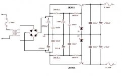
Only a half of this power will be enough, this way your 120VA transformer will be very good, you will have around 30 volts and when hard use voltage will down, lets say...hummmmm, 26 volts. this way things will work very well.
I Made a better circuit, the same, but a little bit cleaner.
Can use it or not, better to use.
Carlos
Attachments
Why would I want to use a Toroidal Transformer over a Standard Transformer? I ask this because I notice in most AMPS I have seen pictures of posted on this board and others that the transformers are Torodial but the Toroidal Transformer from above looks allot more complicated to use than the other kind which is why I am looking away from it, cause I am still not sure what kind of power I need to supply this amp. I hope it's a simple as positive 20v and negtive/ground... I don't know any thing bout negitive voltages like -20 nor how to achieve them :-/
I'll try emailing the guy I bought the kit from and see what he says. I would have done this earlier but I have been hesitant since he is away.. maybe he is checking his mail still though.
I'll try emailing the guy I bought the kit from and see what he says. I would have done this earlier but I have been hesitant since he is away.. maybe he is checking his mail still though.
I can understand that toroidal may be better someway
Just because whole forum is using it.... you may go to chip amps forum, because there's a lot of good information there.
Try to read entire forum... will take 100 hours reading...many days.
People say toroidal more efficient, also use some better magnetic material, some kind of ferrite material... also friends inform me that magnetic field stays alike "insulated" inside transformer hole,and not interfer too much with some circuits that is near it.
In my country is not too much used, we can find, but people do not like, they prefer the standard old transformer, shielded and golden brigth material, with screws and no plastic on it...also you do not see turns.
I also do not like the mounting brackets.... those U.F.O. unindentified flying objects.... really,.. aaaaagh!.
But they are better, this way i do not discuss, technology is growing fast.... very good when used in radio frequency transmiters, better result in RF PA amplifiers...always better...... also smaller, also not too high, helpfull to make small amplifiers. n
You now, i think Eva is the one that talks related to electricity better in this forum.... write Help Eva!.... she is not easy to answer, but she may like you.
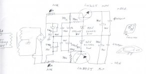
My young friend, i put a schematic up... there, you can understand clearly how to obtains plus, minus and ground with a transformer.... must measure resistance in secondary to be shure where the extreme points are (primary, mains conection has bigger resistance values than secondary, where voltage is reduced).,bigger resistance will find when you hold extremes coil wires (the ones that goes to the bridge rectifier... ground will go direct to condenser junction)..... the third wire will be ground...lets see...hum..... 10 plus 10 ohms measuring three wires, two each time with an ohmeter... resistance scale, low resistance, reading X1, or digital 200 ohms resistance scale. Measuring 10 ohms and 10 ohms, you will discover the one is common for both measurements... this one will be the ground. Resistance will be variable, can be 50 ohms, or 1.2 ohms, depends of the transformer power.
Must conected in a bridge rectifier, have to buy one that can hold more voltage than you need and better to be 3 or 5 times more powerfull related current you will need... have a 10 amperes bridge rectifier.
The way to wire them is showed in schematics.... but primary, the mains voltage will need some friend better qualified to give you assistance first time to discover how to connect input mains wires.
Some transformer have a lot of inputs: 110 Volts, 125 Volts, 220 Volts, 240 Volts... this way may be confused. Need assistance near you, together, sitting at your side.
I am too distant.. sorry, cannot sit with you, unfortunattelly because i like beginners very much.
Just because whole forum is using it.... you may go to chip amps forum, because there's a lot of good information there.
Try to read entire forum... will take 100 hours reading...many days.
People say toroidal more efficient, also use some better magnetic material, some kind of ferrite material... also friends inform me that magnetic field stays alike "insulated" inside transformer hole,and not interfer too much with some circuits that is near it.
In my country is not too much used, we can find, but people do not like, they prefer the standard old transformer, shielded and golden brigth material, with screws and no plastic on it...also you do not see turns.
I also do not like the mounting brackets.... those U.F.O. unindentified flying objects.... really,.. aaaaagh!.
But they are better, this way i do not discuss, technology is growing fast.... very good when used in radio frequency transmiters, better result in RF PA amplifiers...always better...... also smaller, also not too high, helpfull to make small amplifiers. n
You now, i think Eva is the one that talks related to electricity better in this forum.... write Help Eva!.... she is not easy to answer, but she may like you.
My young friend, i put a schematic up... there, you can understand clearly how to obtains plus, minus and ground with a transformer.... must measure resistance in secondary to be shure where the extreme points are (primary, mains conection has bigger resistance values than secondary, where voltage is reduced).,bigger resistance will find when you hold extremes coil wires (the ones that goes to the bridge rectifier... ground will go direct to condenser junction)..... the third wire will be ground...lets see...hum..... 10 plus 10 ohms measuring three wires, two each time with an ohmeter... resistance scale, low resistance, reading X1, or digital 200 ohms resistance scale. Measuring 10 ohms and 10 ohms, you will discover the one is common for both measurements... this one will be the ground. Resistance will be variable, can be 50 ohms, or 1.2 ohms, depends of the transformer power.
Must conected in a bridge rectifier, have to buy one that can hold more voltage than you need and better to be 3 or 5 times more powerfull related current you will need... have a 10 amperes bridge rectifier.
The way to wire them is showed in schematics.... but primary, the mains voltage will need some friend better qualified to give you assistance first time to discover how to connect input mains wires.
Some transformer have a lot of inputs: 110 Volts, 125 Volts, 220 Volts, 240 Volts... this way may be confused. Need assistance near you, together, sitting at your side.
I am too distant.. sorry, cannot sit with you, unfortunattelly because i like beginners very much.
Re: Re: "That man talk about worry"
Well you need to learn fast. You've ordered a stereo amplifier
for a single driver so it will need to be bridged and if you
bridge it output is not what your asking for.
You'd be a lot better off buying the part recommended that
does the job well at a bargain price and analysing how it
works, its power supply etc, i.e. take mesurements etc.
I suggest you do this and use the stereo amp in a different project.
sreten.
Maples said:
No, it's not like that. Sorry. I have a great interest in Audio and I decided to build an AMP myself. I order a Kit so I need to just get a power supply for it (got the crossover already worked out).
Thats why I am asking about a transformer. I thank you all for showing me that AMP from AEC but I want to build this one so I can learn.
Well you need to learn fast. You've ordered a stereo amplifier
for a single driver so it will need to be bridged and if you
bridge it output is not what your asking for.
You'd be a lot better off buying the part recommended that
does the job well at a bargain price and analysing how it
works, its power supply etc, i.e. take mesurements etc.
I suggest you do this and use the stereo amp in a different project.
sreten.Ok people things just got allot simplier for this project, I recieved the kit today and in it were plans/schematics for the powersupply unit I should use! How nice of them
Two questions:
1 - It calls for a bridge rectifier of 10A rating, I've found one at Partsexpress but it's 400V 25A, is that OK or must I get exactly 10A?
2 - It also calls for a 20-0-20VAC Powersupply, anyone know where I can find one for a good price? Partsexpress wants $39 for a 22V+22V TOROIDAL TRANSFORMER - that seems OK to me but I want to buy the rest of the parts I need from just one online store and they don't have the 35V Caps I need....
- Status
- This old topic is closed. If you want to reopen this topic, contact a moderator using the "Report Post" button.
- Home
- Amplifiers
- Solid State
- Need a power a 40Watt RMS Sub...