No problem, carry on
Mike
I made another silly assumption. I was thinking that other 12A_7 tubes would have higher plate resistance than the 12AX7. In fact they have much smaller values so I will need to adjust my voltage divider in order to make my power supply usable with a wider range of tubes.
work.work.work.
Yes, use a regulator as mentioned. A simple MOSFET follower type regulator costs maybe $2 to build, $4-5 if you go all out.
Is this a regulator for the B+? I've never seen one.
I tried a regulator on my heaters and there wasn't enough current.
regulator is a circuit, not so much a component. if you want a simple circuit use zener diodes or voltage regulator tubes, mosfet follower would be the slightly more complex but more sensitive route what i am proposing below is called a shunt regulator. they are easy to construct and very reliable
two 0D3's or one 0D3 and one 0C3 would do the job (300v vs 255v)
mix and match as you like:
0A3 – 75 volts
0B3 – 90 volts
0C3 – 105 volts
0D3 – 150 volts
for the series, design your 'voltage drop' resistor in the beginning of the circuit for up to 40mA(bit much for a preamp, maybe design for 10 mA) and the tube will do the rest, the tube uses gas emissions to drop voltage, the tube draws at maximum 40 mA and at minimum 0 mA(not recommended) i only have personal experience with the 0C3 tube and it works great. i have three of them in series to regulate my screen voltage down to 315v. screen resistors drop it to 300
a side benefit of using tube regulators is there really cool looking and glow brilliantly
zener diodes work on mostly the same principle except they work under the avalanche effect of diodes
(diodes wont conduct in reverse bias until you go past the 'breakdown' voltage, then they conduct very well, until the voltage drops below the breakdown again, zener diodes are designed to function this way)
if you need more explanation for the circuit i can add more information later.
Is this a regulator for the B+? I've never seen one.
I tried a regulator on my heaters and there wasn't enough current.
As Ryuji says...gas regulator tubes or zener chain
The gas regulator tubes are still available NOS from places like pacifictv.
A more complex approach for HV regulation is something like the Maida regulator which was alluded to earlier here.
Google maida or HV regulator and you'll find lots.
For example, this one by Giame Ugliano which has the image you need to make your PCB.
If you look at the 'Red Light District' amp there's lots of info on HV regulation.
For your heaters, you could consider a SMPS 12v supply module (most are adjustable so you can dial in 12.6v). Not very DIY, but a pretty cheap solution. 3A cost $15, 5A $20 or so.
Like this one which I bought recently. Looked at the output on the scope and it seemed pretty clean, though I haven't actually used it in a project yet.
i run the 15 amp version of similar/same design. works beautifully in my amp (yea... i needed that much currentFor your heaters, you could consider a SMPS 12v supply module (most are adjustable so you can dial in 12.6v). Not very DIY, but a pretty cheap solution. 3A cost $15, 5A $20 or so.
Like this one which I bought recently. Looked at the output on the scope and it seemed pretty clean, though I haven't actually used it in a project yet.
 )
)edit:
here it is http://cgi.ebay.com/Universal-DC-12...187?pt=LH_DefaultDomain_0&hash=item3efefa1753
Yes, a B+ regulator. It's quite simple once you figure it out. In the attached picture, B+ comes in on the left. The LND150 acts as a constant current source with a current of approximately 0.6ma. This goes through a 500K resistor to give a 300v drop, providing a stable 300v reference voltage. That voltage feeds through a 50k resistor and 22uf cap which provides a "slow start" to slowly ramp up the voltage while the heaters warm up. The reference voltage is then fed to the gate of a MOSFET. I chose an IRF830, but any high voltage, high current MOSFET should work. The .1uf cap is for stability, you don't need much capacitance here. The voltage divider network on the output serves three purposes - bleed off the capacitors, drive an LED for power indication, and give a voltage reference of approximately 70 volts for "heater lift". The diodes are 1N4004 diodes used for safety to make sure nothing gets reverse biased when powering down.
Attachments
circuit looks pretty simple. keep in mind that the mosfets are dropping voltage as a voltage follower, so keep how hot they are getting in mind/put heat sinks on them
edit:
please dont touch them when they are running to 'see how hot they are' use a thermocouple
edit:
please dont touch them when they are running to 'see how hot they are' use a thermocouple
Last edited:
Yes, a B+ regulator. It's quite simple once you figure it out. In the attached picture, B+ comes in on the left. The LND150 acts as a constant current source with a current of approximately 0.6ma. This goes through a 500K resistor to give a 300v drop, providing a stable 300v reference voltage. That voltage feeds through a 50k resistor and 22uf cap which provides a "slow start" to slowly ramp up the voltage while the heaters warm up. The reference voltage is then fed to the gate of a MOSFET. I chose an IRF830, but any high voltage, high current MOSFET should work. The .1uf cap is for stability, you don't need much capacitance here. The voltage divider network on the output serves three purposes - bleed off the capacitors, drive an LED for power indication, and give a voltage reference of approximately 70 volts for "heater lift". The diodes are 1N4004 diodes used for safety to make sure nothing gets reverse biased when powering down.
This looks pretty cool. The effort you put into this post is most appreciated. I have been thinking about picking up some high voltage transistors to use as followers and such. Thanks!
please don't touch them when they are running to 'see how hot they are' use a thermocouple
+1
Thermocouple or something like this $15 IR thermometer.
I was amazed (at the price- and there are cheaper units available) that it actually works very well - compared results to thermocouple-type and there's fairly good agreement.
Good for monitoring power resistors, heat sinks, etc...
Hi
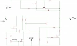
Since you have a 16V source, and I assume the heater source is grounded common to the circuit, why could you not use that to supply a simple low voltage regulator to drive a mosfet shunt with a floating CCS? Perhaps something like this......
Determaining the resistor values should be no big issue, and some of them would depend on J-fets used. If the CCS mosfet is not dropping much voltage, it may not need heatsinked. Most of the shunt power can be dropped in a ballast resistor in series with the shunt mosfet drain. The first cap provides voltage ramp up of the reference voltage. Forgot a bleeder resistor tho.
PS I'm sure you already know this but just to point out you must leave adequate safety space for the HV section.
Attachments
Last edited:
Right now I don't have the components to do the transistor regulator but you guys have given me some cool options. It will definitely be on my to do list. My attempts at a voltage divider worked but the parallel resistor got super hot. I decided to just use a bridge rectifier and live with 180 volts (under load) until I get the parts to regulate the B+. I must admit that the bridge rectified version sounded just fine. I also put two 1n4007 diodes (in opposite directions} on one side of the heater winding and that dropped my voltage to 13.4VAC under load. This should be safe for now but I might experiment with other diodes in the future to get it down even more.
As much as I try to be careful I didn't realize how hot the resistor divider would get and I got a little blister when I tried to dismantle it. Lesson learned. I may need to buy a couple different heat sinks and apply them to anything that looks like it could get hot!
As much as I try to be careful I didn't realize how hot the resistor divider would get and I got a little blister when I tried to dismantle it. Lesson learned. I may need to buy a couple different heat sinks and apply them to anything that looks like it could get hot!
some people have reported running 12a_7 tubes on as little as 80v. might want to try out 12au7 or 12at7 tubes too, looking at 12ax7 load lines, your still in good shape for linearity at that operating point. heres my collection of decent datasheets for the series
http://ryujiwarui.com/data/12ax7-rca1962.pdf
http://ryujiwarui.com/data/12at7-rca1954.pdf
http://ryujiwarui.com/data/12au7a-rca1961.pdf
just because the maximum is 300v doesnt mean you have to run it at that
http://ryujiwarui.com/data/12ax7-rca1962.pdf
http://ryujiwarui.com/data/12at7-rca1954.pdf
http://ryujiwarui.com/data/12au7a-rca1961.pdf
just because the maximum is 300v doesnt mean you have to run it at that
Last edited:
- Status
- This old topic is closed. If you want to reopen this topic, contact a moderator using the "Report Post" button.
- Home
- Amplifiers
- Tubes / Valves
- Need a little help with a power supply I designed.