I'm working on it for a dear friend and I just want the sound to be perfect for him.
Ok, good luck, and be careful.
Yes thats what I thought. So how are you connecting the new circuit ? Are you connecting the source to your circuit, and then feeding the output of that into the power amp in connector ?
The circuit I copied from the amp itself! With great difficulty!
Its a basic design really few caps 2x opamps ne5534 and a huge toroidal. I dont understand the rest.
I'm not fitting anything just trying to improve whats there already in the amp. Just sounds a but bright and low bass. Both me and my pal like warm amps so adjusting to both our taste
")
Ok, good luck, and be careful.
Thanks!! I have been electrocuted 4 times from same amp before!! I try to limit my efforts lately due to potential death of not knowing LOL
Ahh, i see.. youre modifying a circuit in place..
wow.. 15dB is a LOT of gain.. i'd be tempted to VASTLY reduce this down to 6dB and with lower overall resistance values. I reckon that'd probably improve the quality alone, and your volume control on the amp would be MUCH less fierce. I bet it's very twitchy as it is now.
This amp might well date from before CD players... tuners for example only output a relatively quiet 300mV RMS compared to the 2V RMS most CD players and other "line out" sources can generate.
Ahh, i see.. youre modifying a circuit in place..
wow.. 15dB is a LOT of gain.. i'd be tempted to VASTLY reduce this down to 6dB and with lower overall resistance values. I reckon that'd probably improve the quality alone, and your volume control on the amp would be MUCH less fierce. I bet it's very twitchy as it is now.
This amp might well date from before CD players... tuners for example only output a relatively quiet 300mV RMS compared to the 2V RMS most CD players and other "line out" sources can generate.
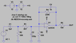
The circuit I copied is the preamp section with no mods as I have:
1, never copied a circuit before with such accuracy!
2, have no idea what does what!
All I want is to reduce high frequency and increase low frequency. And I believe the solution was presented by increasing 30k to 100k (which did add bass)
and 2, to increase 220pf to something higher to reduce high frequency (yet to be tested)
Volume is actually quite gradual and fine!
OK, well.. here's the original circuit modelled in spice, with an AC analysis graph:
The -3dB frequencies are 2.37Hz, and 152KHz. Not too bad. There's only about 3.2mV of output offset which is also low. Not bad considering there is no blocking capacitor in the feedback path.
The -3dB frequencies are 2.37Hz, and 152KHz. Not too bad. There's only about 3.2mV of output offset which is also low. Not bad considering there is no blocking capacitor in the feedback path.
Attachments
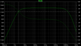
By increasing R2 to 100K, we get a -3dB cutoff of 0.719Hz. However, this then causes the DC offset to shoot to -200mV - BAD.
Much better DC wise, is to increase the 2u2 to 4u7 or 10u. That will lower the LF -3dB cutoff point, and wont interfere with the DC conditions of the circuit
Much better DC wise, is to increase the 2u2 to 4u7 or 10u. That will lower the LF -3dB cutoff point, and wont interfere with the DC conditions of the circuit
the 1pF capacitor (c4) is there for stability purposes... though to be honest, it isnt really doing anything, and you can probably just remove it. If you want to decrease the -3dB HF rolloff point, increase C2 from 220pF. Try 330pF or 470pF.
I've been eagerly waiting on your expertise and from what you say for me to get the desired sound "warm" would be to try increase c2. Hoping the less treble will appear to sound as more bass!?
OK, well.. here's the original circuit modelled in spice, with an AC analysis graph:
The -3dB frequencies are 2.37Hz, and 152KHz. Not too bad. There's only about 3.2mV of output offset which is also low. Not bad considering there is no blocking capacitor in the feedback path.
Bit confused by this. The 2.2uf is bipolar film and is audio input from volume control pot
I've been eagerly waiting on your expertise and from what you say for me to get the desired sound "warm" would be to try increase c2. Hoping the less treble will appear to sound as more bass!?
No.. the -3dB HF is not really a treble boost or cut, it is a bandwidth limit. What you might find on older gear is that high frequency crap from things like mobile phones can get in and distort the signal. Limiting the HF bandwidth of the circuit can help with this. If that's not an issue, I would leave it alone.
Bit confused by this. The 2.2uf is bipolar film and is audio input from volume control pot
OK, i showed an electrolytic capacitor as that's commonly used. It doesnt really matter.
Try a 4u7 polyester cap such as a Wima MKS2. I think that will give you a result you are happy with.
OK, i showed an electrolytic capacitor as that's commonly used. It doesnt really matter.
Try a 4u7 polyester cap such as a Wima MKS2. I think that will give you a result you are happy with.
Ok. This will give me lower frequencies?
But can I still add a few pf to the 1pf to reduce high frequency?
Ok. This will give me lower frequencies?
But can I still add a few pf to the 1pf to reduce high frequency?
4u7 for C1 will give you a -3dB LF cutoff of 1.12Hz. Much lower than the original. I'd say you'll be happy with that.
If you REALLY want to play with C4 id suggest a 2p2 capacitor of good quality. I wouldn't use a silvered mica as they are physically large and you'll have more problems with stray pickup. Use a ceramic capacitor with NP0/C0G dielectric.
Likewise, if C2 is a ceramic capacitor, change it out for a 220pF ceramic with NP0/C0G dielectric. If it's a film capacitor, leave it alone.
OK. I don't even know if I have anything of that low value. Yes its some form of film with no brand. Again!
It is a decent amp just bright that's all! Go maplins if I get a chance! Thanks for advice

Forget Maplin.. theyre a load of **** for parts these days. Try Electronic Components from Rapid - the Electronic Parts Specialist | Rapid Online
Same circuit can the high frequency be lowered?
Just wondering since low frequency can be increased was wondering if high frequency can be decreased?
Look up Baxandall tone controls.
Look up Baxandall tone controls.
Yes i was wondering if maybe a bass/treble control would be more help here
- Status
- This old topic is closed. If you want to reopen this topic, contact a moderator using the "Report Post" button.
- Home
- Source & Line
- Analog Line Level
- NE5534 circuit. I need more bass. Help!!