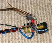
That was understood. The point was to draw your attention to the problems using parts optimised for PCBs in the style of hand (or "hard") wiring. In an ideal world, we could still buy old style components that were big and intended to be hand wired. Today's tiny parts just seem odd; lying belly-up with their legs in the air, so to speak.....I actually intend to use no bread board at all. Just a block of wood with chiseled & pre-drilled holes.
Mount the components upside down & secured with glue & hard wired with spare silver wire from the top.....
Other posts have dismissed these chip quality speculations as nonsense and rightly so. If you accepted all DIY and industry press scuttlebut on face value, you'd never buy any product without being skeptical of performance or in fear of some dire consequence.I noticed there seemed to be a disprorational no of issues with the LM1875 component. I Find this quite disturbing.....
I've used LM1875 chips occasionally for over 20 years and new (bought last month) stock still performs identically to the first ones I used, which I have had to replace. However, in the audio field, I'm used to people relying on their long-term memories and expectancy bias to compare sound quality on repairs I return to them. It's quite amusing hearing people talk like I should believe their constantly changing experiences as if each was an immutable fact. I also think that our health, moods and number of listening hours already clocked up make bigger differences to how we percieve both recorded and live music.
So when someone starts to wax lyrical about their listening comparisons with nominally similar components, I know to only pay polite attention since their methodology is usually about as reliable as a Mickey Mouse watch. If we are really serious about comparing monolithic chip sound quality, we would need some pretty extreme statistical evalutions to do so. That level of process testing is way beyond the scope of DIY capablity and probably much less significant than the other variables of the build such as power supply, preamplifier, grounding, wiring layout and component types.
I'm not saying that listener impressions aren't important, just that they have to interpreted with their extreme variability and limitations completely understood.

It still makes sense to me. I mean there are the TDA2030, TDA2040, TDA2050. Why bother making the TDA2030? If you have a manufacturing process to make the better grade pin compatible chips, why bother making the lousy ones? Line change overs are tedious and costly.
I did a google search to see if anyone had pictures of TDA2030-50 dies and came up empty. I may have a couple floating around. It may have some value to take a couple apart for a look see.
With a successful decapping you might see the part number right on the die. The TDA2050 might have a reworked output stage as it can make about 1.5 watts more than the TDA2040 on the same power supply.
BTW, ST discontinued about half of their analog audio power amp ICs a few months back. The venerable TDA2030/40/50 series got the axe.
Binning is specified in the datasheets.
On products designed within the past decade, I've seen binning only on discrete devices. STD03N/STD03P are binned according to the hfe. However, for ICs, binning really is a thing of the past. That's not to say that you cannot find a modern IC binned into a "high grade" and a "low grade" but it's the exception rather than the rule due to cost reasons. Binning is much, much less common than it used to be. Processes (both design and manufacturing) have improved tremendously since the 1970ies, ya know...
")
~Tom
The offset is up to 10 mV and with a typical value of 1 mV so if you have set the gain to 30 the output offset will be 30 mV and worst case 300 mV.Dear Mr L
I can understand that you would assume that I am making that assumption. But you are replying to one assumption with another. YES this is the most likely situation but are you guessing or do actually
KNOW? Assumptons can be dangerous. According to the meticulous measurement of the LM chips by Peter Daniel they of the same batch can vary significantly more than the 10-30 mV DC offset recommended by Chip Amp as optimum in the instruction PDF for the Lm1875 kit.
Cheers Theaudiopath
It perfectly natural to expect 0-300 mV offset.
Thankyou Mr Bel
.So what do you look for in a batch of LM1875's as the determining factor(s) for audio quality?
Thankyou Mr path
After a quick flip through your DIY history it is indeed clear that you do knowMr. Path,
Yes, actually I DO know. I talk to NS/TI folks on an ongoing basis. Also, I wouldn't take DC offset voltage variation within a batch of devices as any indicator of differing audio quality.
.So what do you look for in a batch of LM1875's as the determining factor(s) for audio quality?
Thankyou Mr path
On products designed within the past decade, I've seen binning only on discrete devices. STD03N/STD03P are binned according to the hfe. However, for ICs, binning really is a thing of the past. That's not to say that you cannot find a modern IC binned into a "high grade" and a "low grade" but it's the exception rather than the rule due to cost reasons. Binning is much, much less common than it used to be. Processes (both design and manufacturing) have improved tremendously since the 1970ies, ya know...
~Tom
What I meant to say was, for example, binning is used in LED production for luminous flux and forward voltage. Binning is part of the inline production process. It's well documented in datasheets so designers can make engineering choices.
On the other hand I did hear a story from a QA of a large CD manufacturer, they needed some discs for the corporate jet, batches of discs were extensively tested and only the best were used.
Last edited:
Hi Peranders
How if at All would the worst case offset
affect audible subjective sound quality?as opposed to the optimum offset .
Cheers Mark
The offset is up to 10 mV and with a typical value of 1 mV so if you have set the gain to 30 the output offset will be 30 mV and worst case 300 mV.
It perfectly natural to expect 0-300 mV offset.
How if at All would the worst case offset
affect audible subjective sound quality?as opposed to the optimum offset .
Cheers Mark
Optimum offset is the value that exactly centers the voice coil of your bass driver as this maximises the "linear" excursion range of the driver.
Since driver voice coils seldom are perfectly centered (mfgr. tolerances or even by bad design) there is no way of knowing if a bit of amplifier offset will improve or degrade the VC centering. Assuming a well centered driver, zero offset from amp is best, obviously.
300mV is nothing to worry about too much, it will offset a typical Hifi bass driver by 1mm or so, with an Xmax of 10mm you'd be hard pressed to note any difference in actual performance.
and if Xmax is 2.5mm ?......300mV is nothing to worry about too much, it will offset a typical Hifi bass driver by 1mm or so, with an Xmax of 10mm you'd be hard pressed to note any difference in actual performance.
You might have problems, then, depending on the driver.and if Xmax is 2.5mm ?
It all comes down to Re, force factor (BL) and spring constant (Cms) whether stealing some of the Xmax is relevant or not.
I = Vofs / Re
F = B*L * I
Xofs = F * Cms
If Xofs << Xmax, say, less than 10% of it : not really a problem.
BTW, ST discontinued about half of their analog audio power amp ICs a few months back. The venerable TDA2030/40/50 series got the axe.
Yup, but significant stock is still in the pipeline as of now. I bought a small quantity of the TDA2050 at 60c/unit last week, and will stockpile more once I confirm that it is a drop-in replacement for the LM1875 (maybe with minor changes to rail voltages and compensation values) in the MiniRef:
http://www.diyaudio.com/forums/chip-amps/184165-miniref-schematic-pcb-layout.html
Good thing someone actually told me as I intend to use with Fountek FE85 (X-Max 1.5 mm) in a 4 speaker line array. So my initial idea of buying at least 6-10 chips to find 2 that match was a good one. Thanks to you I now have a clue as to why. On that note what are the most important matching criteria for the chips aside from the one already mentioned.
I intend to mount each amp on the back of the speaker box to minimize cable length to internal wiring & maximize damping factor.
Cheers Mark.
I intend to mount each amp on the back of the speaker box to minimize cable length to internal wiring & maximize damping factor.
Cheers Mark.
I could be wrong, but I believe that putting in the feedback cap WILL reduce the offset to the chips inherent offset, ie it cancels out the gain at DC. So if you have 10mV inherent offset in the chip itself and 30 X gain you will still only get 10mV offset on the output, not the 300mV that you would get if you omit the feedback cap
It all depends on whether you think that you can hear a sonic difference with the feedback cap in place, and whether you feel that difference is worth it. I'm pretty sure it was one of Doug Self's articles I read that suggested using a bigger than required and on top of that Bipolar capacitor for feedback caps to limit their effect on the sound.
The cap is there for engineering reasons. There may be a tradeoff sonically, you have to make a choice which tradeoff you want. Higher offset, or *potentially* some sonic degredation.
Tony.
Thanks for the reply Tony
There are several other reasons I wish to purchase
a number of chips. So I can try your suggestion and compare directly. There are so many versions, inverted, non inverted, tube buffered, op amp buffered etc. If I like what I hear a surround sound system is there for the building with a few spares if I fry one. An engineer I knew used a triode in the feedback circuit of a 3 watt transistor amp and the little flea powered freak sounded just like a proper all valve triode.I think the feedback circuit sonic signature is often underestimated It Will be fun to try them all & find out for myself.
Cheers Mark.
Please correct me if I am wrong but the driver used has a Fc of 125 hz.
If you build the amp with Ri = 1kR and Ci = 100uF the amp will have a Fc of 1.6 Hz which is way below the Fc of the driver and probably more important at 125Hz the amp will have almost zero phase shift. With this diver it is better to use Ci, you will hear no difference and it will give some protection.
If you build the amp with Ri = 1kR and Ci = 100uF the amp will have a Fc of 1.6 Hz which is way below the Fc of the driver and probably more important at 125Hz the amp will have almost zero phase shift. With this diver it is better to use Ci, you will hear no difference and it will give some protection.
- Status
- This old topic is closed. If you want to reopen this topic, contact a moderator using the "Report Post" button.
- Home
- Amplifiers
- Chip Amps
- National Semiconductor LM series & Ti LM series differences that affect circuit funct