My only reservation with the design is that it appears to me that from the RCA inputs, you'll have variable input impedance from the pot with potential for that number to get very low. I'd much rather have something that always has at least 10K of input impedance.
How is that best accomplished? It looks like the O2 has packed the resistance at the first ground connections. Could that be easily employed here as well?
How is that best accomplished? It looks like the O2 has packed the resistance at the first ground connections. Could that be easily employed here as well?
Will there be any measurements, will it be able to drive everything from small IEMs to AGK K1000, will the be any possibility of group buys ?
(I to slipped of the wire's group buy...)
Based on my research (and inferances), you'll never run worse than 0.05% THD+N on an 8 Ohm load with this design... and that's at the worst measuring area: 20kHz. So this is the best option available on planet earth for the newest uber-IEMs, the K3003. Most headphones will measure about 0.0001% (THD+N at 1kHz) or better at normal listening levels.
I don't expect it to run K1000s very well. You'll want a speaker amp for that.
What about other full size headphones ? (for example the HD800)
0.00003% THD+N. There's nothing better... not even The Wire.
¿Que? I don't think so. The input impedance is rather constant. Can't you explain how you mean?My only reservation with the design is that it appears to me that from the RCA inputs, you'll have variable input impedance from the pot with potential for that number to get very low. I'd much rather have something that always has at least 10K of input impedance.
How is that best accomplished? It looks like the O2 has packed the resistance at the first ground connections. Could that be easily employed here as well?
0.00003% THD+N. There's nothing better... not even The Wire.
i see you quoting national datasheet ideal numbers reached most likely by matching every part (every resistor, everything) in the design including the opamps, rather than measurements of actual amps that people build from digikey strips; about this design quite a lot. I admire your trust
its pretty irrelevant at this level anyway, but i'd like to see the measurements on an actual amp produced from the design files, with standard randomly chosen parts, without an impedance controlled PCB and using an AP system to generate and measure the signal. i doubt very much there would be the same results. in fact you can bet they themselves did not attain that result every time they measured
Last edited:
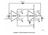
There's also the fact that their distortion measurements were made using their test circuit, NOT the amp circuit.
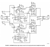
Comparing a test circuit measurement vs a fully built amp such as The Wire is unfair, imo. As you can see in the attachments, the national amp is a bit more complex than their test circuit")
DISTORTION MEASUREMENTS
The LME49710/LME49600’s low residual distortion is an in-put referred internal error. As shown in Figure 3...This datasheet’s THD+N and IMD values were generated using the above described circuit connected to an Audio Precision System Two Cascade.
Comparing a test circuit measurement vs a fully built amp such as The Wire is unfair, imo. As you can see in the attachments, the national amp is a bit more complex than their test circuit
Attachments
haha excellent point! i didnt feel it worth the effort to look into it that far; i had banked on highly controlled conditions for those results, more controlled than a real amp by a real diyer, but this takes that a step further and renders the result meaningless for comparison. IMO its only a step further than taking the ideal distortion models for the 2 parts and adding them together. the noise created by a single 50ohm resistor is higher than the LME49990, there seems to be a few more parts than that in the reference amp circuit. should we take the lme49990 and add it to the buffer measurements and claim that for the wire? seems to me since the lme49990- has lower noise and distortion than the lme49720 it should automatically create a better amp..no?
oh whats that you say?..theres more to it than that?
oh whats that you say?..theres more to it than that?
Last edited:
I would also like to see real world tests. I think we can get ridiculously close to National's numbers. Yes, I have the faith.
Anyway, it's a complex amp and one that costs a lot from a parts perspective. I've wondered what the differences would be with a single LME49740 instead. It appears the PCB routing would have been ugly, but I don't have the experience to make that call.
Anyway, it's a complex amp and one that costs a lot from a parts perspective. I've wondered what the differences would be with a single LME49740 instead. It appears the PCB routing would have been ugly, but I don't have the experience to make that call.
¿Que? I don't think so. The input impedance is rather constant. Can't you explain how you mean?
So about the input impedance, did I miss something? It looks like on the National Reference Design that the potentiometer determines the impedance against the input signal based on its position of rotation. How should I understand the circuit? I am still rather new to this stuff.
 Schematics removed at member's request.
- Status
- This old topic is closed. If you want to reopen this topic, contact a moderator using the "Report Post" button.
- Home
- Amplifiers
- Headphone Systems
- National LME49600 Reference Design Project