
I was very pleased with this as it was identical to an Audio Precission screen grab in an American magazine. 10 kHz this good from class D is not bad. A SE valve amp gives up at 2 kHz often. From memory the Hypex is 47 kHz - 3dB so this wasn't exspected. The Naim Clone I think could beat it. The AP has an add on filter to work with Class D. Note the sine from square at 50 khz. That's fine.
There's plenty of capability there - a fine choice if affordable. It's also quite a tall style at 75 mm but should fit in many varieties of 2U rack case. As a note also to myself, I'll have to think about the placement of the rubber "feet" to ensure the case supports the transformer reliably too. At 400VA +, it's a tad heavy for simply bolting down on unsupported sheet metal. The bottom of the case also acts as a substantial part of the the heatsink so it needs to be thick (≥3mm) aluminium which should solve the problem but may not be easy for everyone. Perhaps it means a Modushop case for European constructors, as suggested earlier......I've requested a quote for the following.....
Continuous power rating: 450VA
Primary: 0-230V @ 50Hz
Electrostatic screen
GOSS Band
3 Secondaries:
2 x 28-0-28V @ 3.57A
1 x 26-0-26V @ 0.96A
Mounting: M8 x 30mm bush in a potted centre
Maximum height: 75mm....
http://www.modushop.biz/site/index.php?route=product/product&path=20_26_74&product_id=100
Last edited:
What you can do is bolt the transformer as usual and then use a rubber pad between lid and transformer top. As heat is an issue not too much side padding. This not only saves money it might damp vibration a bit. If the bolt goes from top to bottom of the case the transformer will get very hot and will fail. It's a shorted turn. The rubber pad helps avoid that also. When the box is slightly taller than the transformer this becomes a real risk. I have done it myself and I felt very stupid.
There's plenty of capability there - a fine choice if affordable. It's also quite a tall style at 75 mm but should fit in many varieties of 2U rack case. As a note also to myself, I'll have to think about the placement of the rubber "feet" to ensure the case supports the transformer reliably too. At 400VA +, it's a tad heavy for simply bolting down on unsupported sheet metal. The bottom of the case also acts as a substantial part of the the heatsink so it needs to be thick (≥3mm) aluminium which should solve the problem but may not be easy for everyone. Perhaps it means a Modushop case for European constructors, as suggested earlier.
Slim Line 02/280 frontale 10mm NERO e coperchi in alluminio 3mm
The quote has come back at £140 GBP, or around $286 AUD.
It's more than I really want to pay but I'll probably go with this - the pair of 225VA 25-0-25V toroidals can go back to RS. They were £90 GBP for the pair so the custom part is quite a bit more expensive, but I'm sure it'll be worth it in the long run and saves me having to worry about a separate supply for the pre-amp.
The case that you referenced (but with solid top panel instead of vented, as per the genuine NAP 200) has already been ordered.
")
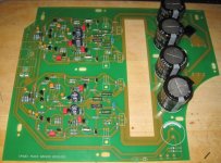
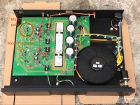
I've almost finished the PCB build, image attached, but progress will now slow down whilst I await the case and transformer. Still yet to figure out how to thermally connect the output transistors to the chassis, a few pieces of aluminium bar will probably suffice. Helpfully the kit came with mica washers for the 2SC2922s, these see to be quite difficult to obtain.
Generally all parts in the kit appear to be of good quality, the resistors have mostly measured exactly the labelled value on my particular ohmmeter.
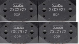
Close-ups of the supplied 2SC2922s are attached. They appear to be genuine, comparable to those included here at least.
Chris
Attachments
Last edited:
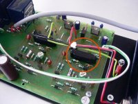
We should try to implement some kind of transistor cap to keep the input pair at stable temperature. There is mounting holes for that on the PCB. Quote from Naim forum:
''Two very significant ones are the black things that look like a blackcurrent winegum. Unique to Naim and arrived with the NAP500, and then found their way into all the amps from the NAP150 upwards. They're actually a very simple and elegant transistor housing that ensures a pair of transistors are kept as thermally close to each other as possible. This cured a common problem with closely matched transistor pairs - their matching would vary with differences in temperature with a knock on reduction in performance.''
''Two very significant ones are the black things that look like a blackcurrent winegum. Unique to Naim and arrived with the NAP500, and then found their way into all the amps from the NAP150 upwards. They're actually a very simple and elegant transistor housing that ensures a pair of transistors are kept as thermally close to each other as possible. This cured a common problem with closely matched transistor pairs - their matching would vary with differences in temperature with a knock on reduction in performance.''
Attachments
Does anyone knows if we can buy the original Naim PCB stand-off somewhere?
Thanks
SB
They were like this I think ? RS have other sizes.
MDLSP1-02M-01 | MDLSP1-02M-01, 2mm Nylon Support Post with 2.5mm PCB Hole and 2.5mm Chassis Hole | Richco
Does anyone knows if we can buy the original Naim PCB stand-off somewhere?
Custom made.
We should try to implement some kind of transistor cap to keep the input pair at stable temperature. There is mounting holes for that on the PCB.
I was considering maybe using a piece of flat heat-shrink tubing, but opened up a little and sealed above the transistors.
Something like this could be a starting point. I'm sure there are many other options though.
Not sure how effective such an item would be on these boards without matching the transistors in the same way that Naim, presumably, does. I've certainly not made any attempt to match these transistors, maybe something for future refinement.
Chris
Hello Beograd, nice to see you here.
Hello Oxfordshire, I am everywhere.

I was considering maybe using a piece of flat heat-shrink tubing, but opened up a little and sealed above the transistors.
Something like this could be a starting point. I'm sure there are many other options though.
Not sure how effective such an item would be on these boards without matching the transistors in the same way that Naim, presumably, does. I've certainly not made any attempt to match these transistors, maybe something for future refinement.
Chris
It's no bad idea. Heat compound and tyrap works. You can expoxy join them head to head and then solder in. They show most changes with the lid off. Lid on and 10 minutes music usually makes them stable. Remember Naim force the balance out anyway. Lid on seems all they really need. If you blow cool air one side of the amp you will see offset change. Below 100 mV I doubt it matters. In fact it the offset pulls the speaker cone in speaker distortion should fall a little bit ( very small amount ). DC offset at worst does nothing. It might actually make an amp sound better as it helps the feedback circuit work. 0.1 x 0.1 x 4 = 0.04 watt. That is 100 mV into a 4 ohms speaker.
Tiger of Peterborough UK made me a beautiful Naim style 250VA with preamp windings ( black cotton taped ).
Thanks for this information Nigel - their quote is very competitive and so I've placed an order. Hopefully it should be available in a week or so.
Chris
They didn't buzz and were a few days from quote to in my hands. They won't know me. Adam my friend from Thame ordered them. Let us know how well they work and VA etc. If you quote the part number that would help others. It will be your number, but will give them the nod as to how someone came to them. Give us here your home AC voltage if you can. Mine is often 244 V as it is a 1966 installation for our street when the 240 V standard ( still mets regs ). My friends house built 10 years ago 236V. I am told the USA can be 130 V ( 260 ). If so let your transformer maker know. Check it a few times and be sure the meter isn't wrong. What Tiger could do if wanted is wind a buck coil to bring the voltage down. This allows them to use a standard design. 30 VA 2 amp 15 V should do it. It will be a secondary. No worries as it is isolated and will bring the transformer out of saturation . More important bring the ouput and DC voltage down. Make it clear it is for that use if a buck coil.
The Hypex good graphs were Tiger. We were very short of space so used Dubillier 50V 10 000 uF that have a 63 V surge rating. Not bad I must say. They had about 10 A ripple if I remember. I got about 43V @ 240 VAC so not unlike the Naim.
The Hypex good graphs were Tiger. We were very short of space so used Dubillier 50V 10 000 uF that have a 63 V surge rating. Not bad I must say. They had about 10 A ripple if I remember. I got about 43V @ 240 VAC so not unlike the Naim.
Still yet to figure out how to thermally connect the output transistors to the chassis, a few pieces of aluminium bar will probably suffice.
Chris
Alternatively you can bolt the output devices to the chassis bottom (assuming 3mm or more alu). However this method requires some sort of jig to solder the transistors the correct depth below the board, before the board is fitted. This way the transistor legs poke upwards through the pcb.
Alternatively you can bolt the output devices to the chassis bottom (assuming 3mm or more alu). However this method requires some sort of jig to solder the transistors the correct depth below the board, before the board is fitted. This way the transistor legs poke upwards through the pcb.
Great idea, thanks. I think that would be workable.
Chris
I was considering maybe using a piece of flat heat-shrink tubing, but opened up a little and sealed above the transistors.
Chris
Couldn't you get the Mrs to knit them a little woolly jumper to share?
Alternatively, I think I would try to mod something like this:
(rohs )pvc Car Terminal Cap / Auto Battery Terminal Cover/ Motor Terminal Protector /wire Harness Connector Cover - Buy Electrical Wiring Caps,Wire Cable Cap,Pvc Battery Terminal Cover Product on Alibaba.com
I'd suggest that, but I'd probably end up with a black eye. She's a feisty one.
Those caps look good, or something similar. Only problem with AliExpress is the delivery time, which is normally measured in months...
- Home
- Amplifiers
- Solid State
- NAP-140 Clone Amp Kit on eBay