HI
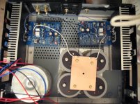
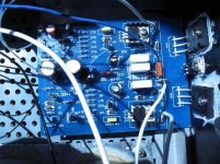
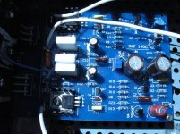
I just finished my Naim clone today . Unfortunately not working .
The quiescent current 15 mA both side even I turn 100 times the trim pot nothing change .
On the speakers terminal one side 26VDC another side 33VDC .
No smoke everithing in the place , the Q1,2 transistors are oposite the solder mask .I use TIP 41 FOR Q5.
I have no idea what to do or were I start to trace the mistake .
I have the blue PC boars .
Any idea please?
Thanks Regards
Attachments
This is just a hunch, if you look over the last 10-20 posts, you will find that 1-2 trans. are incorrectly labelled on the pCB, it should be reverse, go and check.
before powering up(1st time), in order not to damage the o/p trans. I put a series resistor between the power supply and the supply terminal on the PCB, see a few postings back I describe in detail.
before powering up(1st time), in order not to damage the o/p trans. I put a series resistor between the power supply and the supply terminal on the PCB, see a few postings back I describe in detail.
gaborbela said:HI
I just finished my Naim clone today . Unfortunately not working .
The quiescent current 15 mA both side even I turn 100 times the trim pot nothing change .
On the speakers terminal one side 26VDC another side 33VDC .
No smoke everithing in the place , the Q1,2 transistors are oposite the solder mask .I use TIP 41 FOR Q5.
I have no idea what to do or were I start to trace the mistake .
I have the blue PC boars .
Any idea please?
Thanks Regards
Are you using 2N5551 or BC546B as Q1 & Q2?
My suggestion(I would do that myself):
1. input shorted.
2. power up the amp.
3. mutimeter set to DC. gnd the negative probe of mutimeter, with the +ve probe you point to the base and emitter of every transistor. Each transistor should be forward bias, ie approx 0.6-0.7v across base and emitter of each trans*. Any variation from these voltage means, transistor not working.
cheers.
* pnp and npn are different, with npn, base is more positive than emitter and the reverse with pnp.
HI
Idid what you advise .
only problem I found at Q1between base and emiter I measure 10V .And Q4 between E &B 0V.
Why .
Why both side the same problem?
Do you think that transistor is dead ?
I'm using +-40 pover supp. That would be to much for these transistors ?
I realy dont know what to do . I think I give up .These not working .
Regards
HI
I connected the input ground were it say signal ground .
These is not a ground problem something no good with these desingn on the PC board .
Everithing is on the place how it must be and not working .
I built several (at least 30)amp but these the first one when I powered up not working .
I was lucky I mesured the output terminal before I connected the speakers .
All I do I will take the capacitors out and the transistors and the rest I trow into the garbage .It just a waste of money and energy .
Regards
Before you throw away, check rail voltages wrt power ground.
Then check continuity from the signal grounds to power supply ground...
I have had a similar problem myself on another amp.
Jumper signal grounds together and then to power supply ground. See if dc offset goes away.
I am recommending this since you see no smoke or damage (usually a good thing and simple problem)
What have you got to lose?
It was night time here I went to bed(2am here) while you were still working.
Try the following before throwing it out.
Looks like I did not add a piece of info prior to measurement. The measurement can be due to the feedback loop.
note that resistors and capacitors are highly unlikely to go wrong. The transistors are the ones that will go wrong ie dead.
1. Remove the feedback loop from the o/p first.
do the measurement as I suggested above.
I don't have the Nap140(I have the cct diagram), suggested voltages for the following transistors,
TR1, collector voltage approx equal to the emitter of the TR4(ie close to 35-37V after volts drop across 220ohm), only 0.6 voltage drop. The emitter voltage for TR1 should be close to "0" volts. Continue measuring the emitter and base voltage on all the trans. to ensure forward bias of 0.6-0.7v.
There is also a possibility that the parts are ok and you MAY have a dry joint somewhere.
HI
I have some good news thanks to John65b .I sorted the signal ground to the main ground and now I only measure at the speaker terminal 35mA . I will have to set up the quiescent current but only tomorrow now already to late .
It looks like woks his idea .
Thanks one more time .
Tomorrow more tests and more info .
Greetings
HI
Finally one side is up , it sound great very deep and huge bass , open mids ....Long time I didn't heard amp sound like these .
I did some modification of course , I use different driver and power transistors from ON semi .
I replaced some of the capacitors to .
Thanks one more time for the help .
All together it was worth to not to give up !
Greetings
I did some modification of course , I use different driver and power transistors from ON semi . I replaced some of the capacitors to .
Are you willing to share your alternative component choices with the rest of us ?
- Home
- Amplifiers
- Solid State
- NAP-140 Clone Amp Kit on eBay