Naim Close H-140
Hello guys,
By listening to the amp i had an open wire coming from PSU 0V line GND and accident happend by touching minus leg on the second bridge rectifier with the open wire.. whole 4 diodes were cracked open and few ms later T250V 5A fuse blew up.
Testing the boards after i had 21V VDC on one of the power amplfiers output and on the same board one of the 2SC5200 got very hot really fast . Finally some troubleshooting with DMM and i replaced A1145, i got it working again, but decided to re-solder 2 2SC5200 output NPN-s. I bought them from Estonian local electronic store.
EDIT: We could'nt zoom into the photo, re-attached them. Click the link below to see full-size.
http://www.upload.ee/image/4245660/21082014990.jpg
http://www.upload.ee/image/4245661/21082014992.jpg
Replacing them affected sound really much... i lost warmness and co-operation of the amplfier boards when in stereo mode by listening music.
I felt like i have two totally different amplifier boards sounding way to different.
HFe was on original japan 2SC5200 88 and 100.
HFe On these where japan origin wasn't mentioned, they were 98 and 98
I changed amplfier output stage back to Japan ones and the everything wen't back in its place where it was at a very beginning: WARM and co-operative.
So called fake 2SC5200 one's from Estonia:


http://www.upload.ee/image/4245668/040920141022.jpg
http://www.upload.ee/image/4245669/040920141023.jpg
Doesnt look like fake from the inside view but the actual prupose of this transistor is not the amplifier outputstage for sure.
Is there a chance that the one of the Original Japan output transistor 2SC5200 got damage by an early mentioned accident ? the 21VDC on the output.... Sounding is still good and i really cant tell different's in it after replacing A1145 and using amps with the original 2SC5200's.
Right now, i got 95% assembled and working.

http://www.upload.ee/image/4245663/310820141004.jpg
I followed post 7 on the "understanding starground DIY" forum (4mm diameter copper wire was used as a groundbus). It made the hum lowest possible when using potentiometer, without pot it is just shhhh, no hum.
Also, when connectiong starground wire to the actual AC ground(EARTH) i get some spikes on the speakers output when measuring with the Osilloscope.
The starground connection is not grounded anymore to the EARTH, only the AMP case is connected to the AC ground(EARTH).
Last edited:
Hi rensli
A couple of comments. First, your loose wiring problem is a lesson to all DIYs who should take note and learn to use secure connections.
I see from your pic, these are H140 kits. Like some NAP 140 kits, every transistor is a substitute type and these vary between batches and suppliers so what you receive may be a random selection and even then, you cannot be certain those types are true even to their own label. It becomes impossible to discuss problems, even knowing what parts markings yours have, because fakes are something we cannot predict or guess about from pics that really don't show much. Even your supplier probably doesn't know what he is selling you but likely "Hifidiy.net" (whose PCB design H140 is) have an idea but can't take responsibility for kits that may have been copied or assembled by anyone.
Some H140 kits I have seen, appear to have the cheapest available types from generic (and possibly counterfeit) manufacturers. Also, there are no protection circuits, which may reduce costs but this leaves your amplifier prone to disasters when you short connections, as you found out. We may argue that current limiting affects sound and it can, at high output levels but the statement makes no sense, since all NAP models were built with them originally and that is how they were when the brand achieved its reputation for high sound quality. Without any protection at all, your amplifiers and speakers remain prone to severe damage. Perhaps you take care but many users soon forget. Uninsulated banana plugs and bare wire binding posts, for example, are a disaster waiting to occur.
I have heard Naim clones with many different output transistor types but they don't seem to make a significant difference to the sound (those that survive a few watts power, that is). Significant sound differences are caused by bad choice of VAS transistors and wrong compensation caps - as discussed may times in this thread.
Globally, locations that don't have authorized parts sellers are likely trading in counterfeit or generic clone parts. Your source of parts is by your choice and unfortunately, we all seem to have learn this cruel lesson as individuals - the hard and expensive way. Use authorized parts sellers - don't rely on irresponsible or dishonest traders.
Re: earth connections, you may be aware that other parts of you system could already be earthed. Making more than one system connection to mains earth can give rise to hum by forming hum loops in the system ground wiring - particularly when the components use different power sockets. I don't know what type of oscilloscope you are using but conventional analogue scopes are always earthed to mains (or protective earth) at their probe ground, so observing the behaviour of different earth connections is not as simple as you may think.
Check this guide and site for confirmation on wiring and absolutely everything about amplifiers:
Power Supply Wiring Guidelines.
Enjoy your music.
Hello guys,
By listening to the amp i had an open wire coming from PSU 0V line GND and accident happend by touching minus leg on the second bridge rectifier with the open wire.. whole 4 diodes were cracked open and few ms later T250V 5A fuse blew up.
Testing the boards after i had 21V VDC on one of the power amplfiers output and on the same board one of the 2SC5200 got very hot really fast . Finally some troubleshooting with DMM and i replaced A1145, i got it working again, but decided to re-solder 2 2SC5200 output NPN-s. I bought them from Estonian local electronic store.
EDIT: We could'nt zoom into the photo, re-attached them. Click the link below to see full-size.
http://www.upload.ee/image/4245660/21082014990.jpg
http://www.upload.ee/image/4245661/21082014992.jpg
Replacing them affected sound really much... i lost warmness and co-operation of the amplfier boards when in stereo mode by listening music.
I felt like i have two totally different amplifier boards sounding way to different.
HFe was on original japan 2SC5200 88 and 100.
HFe On these where japan origin wasn't mentioned, they were 98 and 98
I changed amplfier output stage back to Japan ones and the everything wen't back in its place where it was at a very beginning: WARM and co-operative.
So called fake 2SC5200 one's from Estonia:
http://www.upload.ee/image/4245668/040920141022.jpg
http://www.upload.ee/image/4245669/040920141023.jpg
Doesnt look like fake from the inside view but the actual prupose of this transistor is not the amplifier outputstage for sure.
Is there a chance that the one of the Original Japan output transistor 2SC5200 got damage by an early mentioned accident ? the 21VDC on the output.... Sounding is still good and i really cant tell different's in it after replacing A1145 and using amps with the original 2SC5200's.
Right now, i got 95% assembled and working.
http://www.upload.ee/image/4245663/310820141004.jpg
I followed post 7 on the "understanding starground DIY" forum (4mm diameter copper wire was used as a groundbus). It made the hum lowest possible when using potentiometer, without pot it is just shhhh, no hum.
Also, when connectiong starground wire to the actual AC ground(EARTH) i get some spikes on the speakers output when measuring with the Osilloscope.
The starground connection is not grounded anymore to the EARTH, only the AMP case is connected to the AC ground(EARTH).
Where did you bought those? I ordered 20 pairs from "ohmsshop" and if they're fake...
I ordered them from ohmshop too... one thing i can tell that they are safe to use, atleast they didn't burn out while listening music at high outputs 
But the sound was more bassy with them... also "drums" where not as wide and open as with the original ones from china (Y). Drums also sounded a little bit like "kilu(estonian phrase) = metallic" I remember i had HI END computer speakers in plastic cases where drums sounded almost like fake 2SC5200-s. More u crank the voltage up, the more dissapointment u get
In terms of wattage, its possible that they can output 100W each without problems...
Another thing, u can see two Heatsinks on this setup(they'r weight and size are same), original output heatsink was HOTTER then the FAKES output heatsink... it might be that Fake's are likely transfering less heat to the heatsink due to poor construction of the transistor... but again by opening it, i was suprised, not any marks of poor quality...
As Ian Finch mentioned, ohmshop themselvs may not be familiar with good or bad 2SC5200's ...
It is possible to perform a rough test on power transistor authenticity by measuring and comparing Ccb (that's simply the non-biased capacitance between base and collector) with a sensitive capacitance meter that can be zero-adjusted. They are not expensive now, but the capacitance ranges in budget DMMs can be too basic and may not give reliable results at readings below 200pF.
Recently I bought some Sanken LAPT power transistors that look suspiciously wrong in their labelling and package moulding. The part number is now generic and several manufacturers produce them with Ccb variation ratio of 10:1! That is only for brands I have tested from Sanken, Inchange, Mospec and at least 2 obvious fake products. I guess there are more out there too.
The OEM specification of Cob is only about 6OpF and this correlates somewhat, with a simply measured Ccb of about 110pF. Generic branded equivalents seem to vary from 200-400pF but fakes like my latest supply, measure a massive average 1.2 nF. They don't perform anything like an LAPT should and are useless in my audio application.
However, you may be aware that the original parts in NAP140 were very high current, old style BDY58 transistors with Ft 7 mHz. Avondale audio clones use MJ15003 with Ft only 4 MHz too but Naim later used much faster 2SC2922 LAPTs. Obviously, if NAIM had no problem substituting such widely different parts, there should not be a problem using genuine Toshiba power transistors, but who knows what was supplied in the kit and from your spare parts supplier?. The actual type should not be critical in the clone amplifiers, as long as it is a type suitable for audio and has sufficient ratings.
Because genuine 2SC5200/1943 are now obsolete, fakes are becoming more common. The genuine replacements are Chinese fab. TTC5200/1943 or the Japanese TO3P version, 2SC5200N/1943N. None of these are expensive, so it seems crazy to try to profit from faking transistors as cheap as genuine 2SC5200 has been for years. Rest assured, there are plenty of similar looking fakes and the issue is not just who you bought them from but who your supplier bought from.
Last edited:
this circuit diagram is where I ended up with mine after doing simulations. After much procrastination kits have been built and are in use, although cases aren't 100% complete.
maybe this circuit diagram could be of help to others thinking of going in a similar direction.
maybe this circuit diagram could be of help to others thinking of going in a similar direction.
Attachments
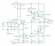
Three "tunings" stand out and probably account for much of the "sound" signature.
R3+C2 set the RF filter quite low @ ~ 100kHz. 10kHz and upwards will be rolled off.
R8+C5 set the Bass filter and as a result generate LF distortion. D.Self explains.
T2 runs @ ~ four times the current of T1. This will result in distortion. D.Self explains.
R3+C2 set the RF filter quite low @ ~ 100kHz. 10kHz and upwards will be rolled off.
R8+C5 set the Bass filter and as a result generate LF distortion. D.Self explains.
T2 runs @ ~ four times the current of T1. This will result in distortion. D.Self explains.
The topology is the same as the RCA design that the Naim and Clones are based on but the parts values chosen mean it will be a long way from the type of sound quality (distortion profile) you may be expecting, as AndrewT refers. It is also highly risky to use those rail voltages and only fleapower BC546/56 for VAS transistors and TIP3055/2955 outputs. You will need at least Vceo= 100V and >1W dissipation ratings at the VAS.
You may have just been lucky with individual parts exceeding their specs or by using an E-I or undersized transformer type. Maybe it does work fine at low levels anyway but a bit of accidental full power + clipping can soon lead to smoke escaping when you have exceeded datasheet ratings. Don't assume simulators give a toss what maximum ratings parts have - everything works!
As it stands with that output stage, lower the rails to 40V or less and use something more capable at the VAS - even a parallel pair, each with their own emitter resistor for current sharing would be better, if the rails are <=40V.
Ian. Sorry to say this , I posted the RCA, it as much resembles a Naim as it does a Sinclair. I contacted Alan Morinington West. He was very annoyed that I did. He is in the Southampton area. From what I could understand the design is completely original and predates almost anything that resembles it. The RCA is far more intriguing and arguably better than anything modern in some areas. The main resemblance of these amps is to LM741 which was a design of 1963 that was suppressed until about 1967 and its designer is credited with the current mirror designs. Gogny's 1967 is similar in some ways and equally intriguing with it's compound 2N3055 Darlingtons to drive 1 ohm.
That RCA slur was I think put around by another famous designer who I would not name ( mostly as I might be wrong ).
I have to thank Naim Audio for loaning Royd Audio a Nait amplifier for the Whittlebury Hi Fi show ( Steve and Paul ) . I was very much deceived by some people. Naim is still very much the sound it always was and now better where it needs to be. I had been told it was a poor relation to the old designs. What absolute nonsense and vicious nonsense at that. Rega also for lending a P6 Excite PU. What a superb combo. My turntable cost 6 times that. I could use the Rega and be very happy. The old Rega wow problem that was acceptable in a cheap design, it is not there in the P6 or whatever it is called.
Has anyone tested mje15030-31 for drivers and mjl21193-94 for outputs? will this combination have any stability issues?
I'm using those, works just fine.
I have turned up no less than 12 similar featured, RCA designed medium power audio designs from the silicon period around 1968 to around 1976 so there is plenty of room for differences between the many variants that could be referred to. I know that I haven't even found all of them yet..... Sorry to say this , I posted the RCA, it as much resembles a Naim as it does a Sinclair....
That RCA slur was I think put around by another famous designer who I would not name ( mostly as I might be wrong )...
However, before Les Wolstonholme removed the image and all his schematic details from his Avondale Audio website ( NCC200 Power Amplifiers ), he proudly pointed out the virtual identical electrical design in comparing NAPs and that one particular RCA design which he incorporated in the promotional details for his NCC 200 amplifier modules. It showed a design published in a 1972 (IIRC) RCA design booklet. I looked closely at it and sure enough, that was as near as could be to Vereker's generic Naim design, and therefore his own Avondale clone - barring the "tweak" caps. and some specific parts values.
You can argue about the sonic qualities of all the tweaks and the nasty imbalance of the LTP or the various semi substitutes in NAPs over the years but the circuit stood for many years as a close copy of Les' RCA book design. I think it is a fair statement, regardless of what people really mean when they say a design is different - are they talking about parts, PCB layout, topology, case, add-ons or something entirely subjective?
Unfortunately, I haven't seen that handbook elsewhere on the web so If Les is able, I'd like to see it to posted here for posterity. Surely, he would have retained the images of his web pages before they were altered in 2013.
Here is the the Waybackmachine image of the page I referred to above. Unfortunately, too small to see all details properly though this is a boostrapped VAS and compensation is applied in an earlier fashion here: https://web.archive.org/web/20120626023447/http://avondaleaudio.com/power-amplifier-module-ncc200/
Last edited:
Is this what you are looking for ?
I *think* it's in here ... but I have never opened it ...

And here, but I'm not signed up
https://openlibrary.org/books/OL5339151M/RCA_solid-state_power_circuits_designer's_handbook
Do bear in mind the extreme amount of work Les Wolstonholme at Avondale Audio did with his own take on the RCA and component selections / recommendations. Unfortunately his take can easily be found on the web and poorly selected (in some cases) copy kits - but his boards are of course spot on, stable and superbly built.
He also sells the most excellent Kendeil capacitors which work very well as the PSU for the circuit and of course many other nice related things.
An externally hosted image should be here but it was not working when we last tested it.
I *think* it's in here ... but I have never opened it ...
And here, but I'm not signed up
https://openlibrary.org/books/OL5339151M/RCA_solid-state_power_circuits_designer's_handbook
Do bear in mind the extreme amount of work Les Wolstonholme at Avondale Audio did with his own take on the RCA and component selections / recommendations. Unfortunately his take can easily be found on the web and poorly selected (in some cases) copy kits - but his boards are of course spot on, stable and superbly built.
He also sells the most excellent Kendeil capacitors which work very well as the PSU for the circuit and of course many other nice related things.
Thanks brianuk, that's the image of the thumbnail previously shown on Les's site, though it's not the same as the NCC200 schematic shown alongside. Other RCA designs or variations from the period had features like the adjustable Vbe multiplier, current sources for the input pair and VAS, Miller compensation.
I haven't sought to compare parts selections or build quality which are different matters but the electronic design of the NCC200 DIY module design shown then, apart from reverting to using an output coil, is the same as the generic 20th century NAP design.
I imagine that handbook was a widely read primer for solid state audio design back around 1970 and many aspiring designers would have referred to it or to Philips, National semi etc. application notes. The original Naim model, NAP200, was a BTL (bridged) design and precursor of the NAP250 so the basic design would have needed to be robust but compact and simple. I think it would have been more obvious which semiconductor manufacturer's school of design you followed as an amateur back then and maybe that's the basis for claiming RCA was the source.
I would say the differences are as large as a US V8 engine and a BMW V8. The similarity will be in the V8 bit.
The Naim long tail pair arrangement is very different which will produce very different harmonic distortion traits. Compensation is different. There is no Baxendale diode to match the two halves when RCA ( quasi PNP ). RCA has an output choke and Naim reject that as a design belief. Biasing also.
I will stick my neck out and say the RCA resembles nothing I can remember and like most designs of the transistor producer might have insights as to best practice.
I hope he doesn't chase me over this. To quote the NAP 250's designer.
" There was no reference to Quad 303, nor an RCA design, nor to the later Sinclair or much else. Amongst the design elements I used NAP used Solitron RF transistors - seecso it's nigh forty years old. Pre-amp (years before CD or usable op-amps) used CCS in emitter followers for low noise, low distortion &c. I left in the early days so know nothing of what followed."
...It is also highly risky to use those rail voltages and only fleapower BC546/56 for VAS transistors and TIP3055/2955 outputs. You will need at least Vceo= 100V and >1W dissipation ratings at the VAS.
I probably should have mentioned all the transistors in my build are as per the kit, the bigger transistors in simulations are substitutes as I don't have the correct models.
I just remembered something John Curl said. He though Harmon Kardon used the RCA circuit before anyone else. Loosely speaking they did. Citation 12 perhaps. Even so the Harmon Looks different.
RCA published plans for the 7199 valve about 1960 if memory is right. This seems to be a specially adapted TV type with a hum shield. The RCA circuit looks much like the Dynaco 70 except I think EL 84 outputs . Not identical. The 7199 having a gain of 300 in it's pentode , enough to do most of the voltage amplification. The triode in the same package doing the phase splitting via a DC coupled gain to splitter. This giving divine simplicity. RCA knowing the most about how to use their own parts. They had not lost the talent when using transistors.
Read the final bit of this if you have time. What an interesting way to do testing.
https://www.passdiy.com/pdf/citation.pdf
- Home
- Amplifiers
- Solid State
- NAP-140 Clone Amp Kit on eBay