You may not have picked the best basic design for an experimental mule. The basic 70's RCA design within a NAP was not particularly pleasant to the ears for a number of reasons but there's nothing wrong with trying other ways to pretty-up the sound quality.
Experience remains the best predictor of what will generally sound good but simulation has only automated the tedium of drafting, measurement and revision. It makes that part of the process accessible to anyone with a will, without necessarily understanding how the electronics work.
One interesting benefit of simulations has been visual aids like the FFT spectrogram. This helps designers define what type of residual distortion sounds best to their target demographic from measurements and then replicate it. Of course, it works just as well for you, once you have a reasonable sound card and dummy load to use for practical measurements. Don't assume that zero distortion appeals in practice as it does in principle. I've met very few audio enthusiasts who prefer really low distortion amps.
Re: On-semi quality.
Sorry to confuse. I was referring to OEM products as far as reliability is concerned. The MPS series are On-semi, the others being Prolectron (European industry), licensed to any serious manufacturer including Fairchild, ST Micro, On-semi. I have no way of knowing what your source of BC546/56 might be.
My Name is not Naim
My Name is not Naim
My Hitachi SR-802 has finally died and there are just too many faults to fix. I am going to buid a Naim 140 chinese clone but use the Hitachi transformer which will give me 45V rails. I am not entirely confident that it will go well but have put a lot of thought into which components I will modify to cope with the extra voltage.
I have a couple of questions for the senior members if they have time to give me a bit of help.
Firstly, should I use the current limiting section and diodes over the output transistors if I intend to use a speaker protection module such as the silicon chip one used on their ULD and 20W A-Class amps, it monitors the speaker output for DC faults, the transformer secondaries for loss of AC (dethump) and the temperature of the heatsink upon which the output transistors are mounted any of these fault conditions will disengage the speaker within a half hour or so!
Do the substitute transistors work well with this design?
Should I forget the whole idea of using this beautiful old shielded transformer and revert to the 2X28V transformer recommended.
I am most interested in comments from members that have built one of these Naim 140 clones or who might know how they work.
Cheers
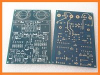
Attachments
http://www.diyaudio.com/forums/solid-state/112453-nap-140-clone-amp-kit-ebay-18.html#post3005564
The over voltage issue was brought up before . Rather than being a problem it is an opportunity . This mimics the ways of the Naim NAP 250 and might be better ( faster ) .
The over voltage issue was brought up before . Rather than being a problem it is an opportunity . This mimics the ways of the Naim NAP 250 and might be better ( faster ) .
Hi,
There is no need to change the voltage, 2x45V is OK if you mean DC and not AC.
I think that most DIY-ers remove the protection section on the boards. If you can use external protection circuit with output relay, I don't see a reason to keep the in-circuit protection. In addition it affects the sound more or less.
About components substitutions: you can read older posts in this thread, there is plenty of information. I wouldn't use any of the semiconductors supplied with the Chinese kits. Actually, what I did was to buy just the boards. I've made 2 pairs of clones so far and both work according to my expectations. I think it's pretty difficult to mess up with this circuit and still many people have troubles.
Regards
Agreed, the higher voltage (Id use no more than 2 x 30VAC) is not an issue for the substitutes used nor most original semis. The clones however, come with a mix of parts that don't really give a pleasing result, (compensation is wrong now unless the ZTX parts specified for the VAS are used) even with 40V rails, so what have you got to lose? Though a lot of people say they just want an amplifier and don't care about the original sound quality, a bad sounding amp remains bad sounding unless you fix the mistakes made in most clones; both in kits and by builders.
The problem for DIYs here is that they are attracted simply by low prices and the 'Naim' but the problems are the same for any amplifier - how to wire it up correctly with the parts supplied and then safely test it. This is where lack of experience kicks in. We can all assemble parts following an illustration but where there is any discrepancy in pinouts, wiring diagrams, parts types & markings, someone will always make an error if possible. The kit suppliers don't often illustrate how safe testing should be done either, so it isn't - not until the smoke rises, it buzzes loudly or there is cold silence - at least that's what I hear from noobs in my area.
The problem faced in use will be with the extra idling heat dissipation. As said before, there is no direct thermal coupling between output stage and the bias controller (Vbe multiplier) TR5. This will grossly affect the bias control, depending on the air volume and position of the PCB in the case which originally was the heatsink. Even so, a 1980s "Chrome Bumper" NAP 140 takes around 20 mins to come to any sort of equilibrium betwween idling and typical 1-5W output levels and I doubt that anyone building in an oversize case with attached heatsinks ever comes close to maintaining correct bias with best sound quality.
If any anyone has the time and determination to address this particular problem simply for NAP clones in general, I'd be interested to pass it on.
Last edited:
Hi Ian,
I have some experience with the Vbe multiplier and I agree with you that its settings and stability affect the sound. In my clones I use TO-126 type transistor that I attach to one of the drivers small heatsink. In this configuration my findings are that the amp is overcompensated and some play with the resistor of 27 ohms should be involved to adjust the idle current properly. And I don't mean just static stability, but mostly the more important dynamic stability during playing. I found that my amps sound better at start-up and then the sound changes and got kind of dull after few hours of use. This problem pointed out to me that good dynamic thermal stability is priority.
This is one of the very difficult things to adjust, considering the variety of transistors that any of us is using. Actually, a friend of mine made the clone with TO-92 trasistor in the Vbe multiplier, and from what I heard, his version sounds better and doesn't change with time like mine.
So my advice is, if one doesn't want to play extensively with the Vbe multiplier, just make the circuit with small TO-92 style transistor as Vbe multiplier. There are more chances to make it right from the first time. Of course, as you said, the size of the main heatsinks and the drivers heatsinks will play a major role as well. It can be optimized experimentally, but I doubt that many people would go into such exercise or that everyone can measure the dynamic bias changes.
In the Self's and Cordell's books there are some good chapters about all these issues...
Regards
Last edited:
that's what I hear from noobs in my area.
Many people like myself, who 'appear' to be new to electronics and yet have struggled with concepts and theory until they eventually got it 100% right, have a lot to offer a forum such as this. These enthusiasts pose valid questions to the 'educated?' engineers & 'experienced?' practitioners, to answer with all their knowledge and experience. Yet, the 'noob' on this particular forum is often left in the dark, like a mushroom waiting for water, or worse still; led up the garden path.
In brief I find the terms; NOOB, ROOKIE, or AMATUER offensive to the Max, weather pointed at an individual, or used as a general characterisation. They suggest an heir of authority on behalf of the name caller. So let's just cut the crap.
I am a certified wood machining tradesman and have made a point of passing on every piece of knowledge I have 'ever' been gifted. This has always worked in my favour when an apprentice comes to me with a new and better way of doing things - which saves me time and effort. I would suggest that this site DIY Audio, is a collaborative effort and we the users occasionally pay for the privelage to pose a question or make a point...With that in mind I offer greetings to my friends and criticisms of the one-per-centers. [Those who exert little effort].
Hi there Ian. Did you look at the pcb? Did you look at the edited sch? After reading your response I doubt it seriously. You have just regurgitated a gut-ful of rhetoric as far as I can see, Just like a turkey regurgitates a cocaroach for its fledgeling. I don't eat 'roach matey!
Why cant you just chime out, if you have nothing helpful to say? You seem to exert huge efforts which rarely produce fruit. I believe this 'over-reach' on your behalf, is transparently used to convince other readers of your intelligence and superior status as an audio guru, and yet I see no evidence of this in the world beyond DIY. It's beyond a joke mate. Have I missed something Ian? Are you on the DIY payroll mate? Yes/No?
The other members who responded to my post, had a more positive and pleasant 'feel' about them, and were enthusiastic for my tiddling little project, They offered encouragement and practical help, and pointed me in the right direction.
Ian French did make one valid point!, about the thermal compensation for the bias section and hinted at a solution. But once again, as usual, he chimed <-in with his 'global commentary' and then out-> with no offers of solution, alternative or encouragement. This makes his response a chore to read, let alone decipher.
What are you on about Ian? Try and break it down into small bytes so the reader can understand what you are trying to say. This thread is not about you mate, so let's get back to the Naim 140 Chinese Clone PCB.
I have already considered the thermal issue that Ian clumsily mentioned, and decided to use a large heatsink from an old defunct receiver. The Naim clone amp boards pictured in post #1162 allow me to mount the output section (including the vbe multiplier) onto the one surface. I have estimated the heatsink's coefficient of ThermRes_4_80-C_rise to be better than 0.5 . My heatsink face measures a quarter over 5" high by 10" wide by 2" deep (the fins are 3/32” thin & spaced 3/8” apart). The logic I used for selection of this particular piece of extruded aluminium is the same used in the Conrad heatsink catalogue that states "a warm heatsink conducts heat with more efficiency than a cold one". This concept requires a bit of time to 'actually' get your head around but it 'is' written! and I believe it to be true.
Where to from here, for my Name project?
- Google Naim 140 and find a picture of the 'guts' of a Naim140 if there is such an animal.
- Find out the optimal bias current for the standard Naim140, and then take a stab at what will be correct for my version.
- Find out why the original designer Julian Vereker MBE used such a heavy set of drivers in the MJE243/253 and reconsider my choice of D669/B648. [My logic for using the D669/B648 is that the device is common and therefore less likely to be bogus]. If I knew who to trust, I would use the original MJE combo, but the duds are coming from left, right and centre. The 'centre' is the manufacturers themselves I suspect. Its a jungle out there!
- I also wonder about the choice of VAS transistors, why do they need to have 2A collector capacity when the current peak is less than 200mA? With all due respect to bandwidth? Do they actually handle that collector current anyway? Or, is there a better more contemporary substitute available? One that is less likely to be a forgery or manufacturer-sourced reject?
Last edited:
So my advice is, if one doesn't want to play extensively with the Vbe multiplier, just make the circuit with small TO-92 style transistor as Vbe multiplier. There are more chances to make it right from the first time. Of course, as you said, the size of the main heatsinks and the drivers heatsinks will play a major role as well. It can be optimized experimentally, but I doubt that many people would go into such exercise or that everyone can measure the dynamic bias changes.
In the Self's and Cordell's books there are some good chapters about all these issues...
Regards
At this stage I am going to use a to92 such as the one on the updated schematic shown above in post #1162.
Can you tell me why you dont have the maple leaf on your flag Ruwe are you an expatriate from Europe?
Cheers
Can you tell me why you dont have the maple leaf on your flag Ruwe are you an expatriate from Europe?
Cheers
Hehe, because I spent about 35 years of my life in Eastern Europe and only 10 in Canada. I still, and probably, will forever feel more European than a Canadian
")
If you have the patience to read this whole thread, I think that you'll find most of the answers that you need. There is not much new to add about this amp, but only to repeat the old stuff. If you have some specific questions about the operation of the circuit or the components, you are more than welcome. The problem is that explaining theory in a thread is in my opinion useless, unless the person asking and the person answering know well each others level in electronic knowledge. In a way it should be interesting for both sides, or people just stop writing
It also takes a lot of space and time. I, personally, try to avoid theory writings, because there are so many resources online and good books as well.This thread is one of the very civilised ones, don't feel offended. The lack of intonation in the writing often masks the real intent of the writer.
As for the static currents in the circuit, the input pair shares about 1.5mA, the VAS about 7-10mA, the drivers may be 5-7mA and the output transistors about 25-30mA. The channel total gives 35-45 mA or thereabouts. If you are way out of that, something is not working properly.
Regards
Firstly, should I use the current limiting section and diodes over the output transistors if I intend to use a speaker protection module such as the silicon chip one used on their ULD and 20W A-Class amps, it monitors the speaker output for DC faults, the transformer secondaries for loss of AC (dethump) and the temperature of the heatsink upon which the output transistors are mounted any of these fault conditions will disengage the speaker within a half hour or so!
Cheers
I had a similar question, and or doubts about the original 60's circuit. So I've spent quite a bit of time simplifying the circuit and running simulations. (Which I know some members are not so fond of). What I haven't done yet is finished the physical construction or any testing - so there's the possibility that it's all nonsense and goes up in smoke.
But any how, if you would like a copy of the circuit diagram, PM me your email and I will send it to you. I'm not intending to post it here until it's tested. Quite a few of the circuits already posted on this thread don't simulate well, and (at this stage) I don't wish to add misinformation.
What I don't particularly have is any opinion about what transistors sound better than others. But it seams logical that some will sound better than others.
I reckon that the forum members here post with good intention, and have wealth of information gained from many years experience that they are happy to share.
Have fun with your project.
Last edited:
As for the static currents in the circuit, the input pair shares about 1.5mA, the VAS about 7-10mA, the drivers may be 5-7mA and the output transistors about 25-30mA. The channel total gives 35-45 mA or thereabouts. If you are way out of that, something is not working properly. Regards
I feel the same way about Tasmania, but it is pretty good up in Queensland.
Back to the amp, If I were to set the output bias current to 40mA, then the voltage across one of the 0.22R resistors would be; .040A x 0.22R = 8.8mV Is this a good place to start?
Cheers.
I reckon that the forum members here post with good intention, and have wealth of information gained from many years experience that they are happy to share.
Have fun with your project.
I am pretty sure I will have fun once I have housed the project and hooked up the speakers - the rest is a means to an end. And no, I don't live in a garbage tin like Oscar the grouch, but I can relate to him more and more these days.
I would like to think that nuclear power is safe, that global warming is a myth and that most people give a damn, but there is a growing body of evidence to the contrary.
Cheer up mate,
with a bit of effort we can change the world for the better. I would like to see that schematic of yours, so could you please send it to me, phil dot j dot elliott at bigpond dot comFarmerJack
I recently tried the Hypex UCD 180 modules at +/- 45 V . They might serve well ? I have the SMPS power unit . I tried it with a conventional PSU ( 2 x 22 000 uF and 500 VA transformer ) and felt it slightly better . Almost zero heat output at 50 watts continuous . The input sensitivity is about 1.4 V . I changed this with excellent results ( 400 mV ) . Whilst I am not the worlds greatest fan of class D Hypex might be an option .
Hypex Electronics BV - UcD180ST
Hypex Electronics BV - UcD180ST
Oh dear.....
No Farmerjack, your guesswork was wrong and the response was a directly offensive tirade, as you obviously intended. This is not your thread any more than others' posting here. We are not your workplace apprentices, remember and don't need to know what peeves you about other member's replies and the world generally. For your information, the noobs I referred to are mostly 12-17 years old and use the term to describe themselves. I clearly did not address any others as noobs here in any degree. Still, if you don't like to read posts from other members, you can always use the ignore button. Just don't make unprovoked personal attacks and post nasty rhetoric here again, please.
If you want blow-by-blow breakdowns on the issues you raise, discussions and references are here to read already. So are whole Forums like Pinkfishmedia and Neil McBride's archived Naim site(s)
If you want to see the internals of NAP140 and other model pics, try this 10 second Google result: Power Amps . There are many more on the web.
You also did miss the point of describing the thermal sensing problem. You described setting up a heatsink with sensor on the output transistors or the sink as in a complementary EF amplifier. This would undercompensate and probably result in thermal runaway. Conversely, Ruwe's use of just the drivers, as in a CFP output stage, led to overcompensation and the bias fell to useless levels.
The quasi-complementary output stage is a hybrid but what to do to get the best compromise of the Vbe multiplier tempco to suit 2 quite different bias control requirements in series? This remains an awkward problem after what, 50+ years? When you have a grip on that, then feel free to tell me what I should know and post about Ebay Naim clones.
87MOSFET
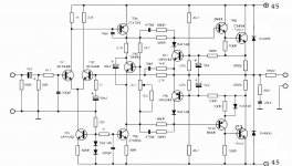
I wish these kits were still available . R3 and R9 tweaked if a lower voltage ( +/- 55 DC original ) . On 45 V R3 becomes 43K and R9 10 K ( 2 W ) . The bias was set by ear if you like . Fingers also . Make VR1 470 R to make it safer . Exicion 10N/P20 ( 10/16 now obsolete ) as outputs and 2N5401 and 5551 as OK substitutes for nowadays . The originals were better . 2SA970 substitutes 2SA872A . H H used MPSA 42 and 92 in their version .
I wish these kits were still available . R3 and R9 tweaked if a lower voltage ( +/- 55 DC original ) . On 45 V R3 becomes 43K and R9 10 K ( 2 W ) . The bias was set by ear if you like . Fingers also . Make VR1 470 R to make it safer . Exicion 10N/P20 ( 10/16 now obsolete ) as outputs and 2N5401 and 5551 as OK substitutes for nowadays . The originals were better . 2SA970 substitutes 2SA872A . H H used MPSA 42 and 92 in their version .
Last edited:
If I were to set the output bias current to 40mA, then the voltage across one of the 0.22R resistors would be; .040A x 0.22R = 8.8mV Is this a good place to start?
Cheers.
Yes, correct. Some people set it even lower to about 5-7mV. The other currents are set by the current sources, so you don't have to do anything about them.
What I don't particularly have is any opinion about what transistors sound better than others. But it seams logical that some will sound better than others.
This is my personal opinion on the elements that affect the most the sound of this amp:
1. VAS transistor in relation with the compensation capacitor in order to squeeze more bandwitdh and speed.
2. The balance of the currents in the input stage, or rather the allowed un-balance from the 22k resistor vs. 1k, and the kind of not properly set total current in the current source. Nigel gave useful input in previous posts on this trick that Naim used to shape the harmonic distortion to their liking.
3. The quality of the feedback capacitor and proper polarity orientation, according to the output DC offset. By quality I mean capacitor with low absorption loss and also capable to behave as a capacitor at hi-frequencies. It's not surprising that Naim chose tantalum. I suspect that OS-CONs may be even better.
4. The output stage as a whole - power transistors, power resistors, current settings and thermal stability. MJL3281 is one good example that I know of. 2SC5200 (if not fake) is another.
The rest of the transistors are small signal ones. BC54x/BC55x, 2SC/2SA, Zetex-es are all good if you choose for high gain, high bandwidth, low output capacitance and noise. I tried several types and honestly I don't hear any difference.
The drivers MJE243/MJE253 are tested and stable. I don't think they add much to the sound. There are many others and they will probably work fine. With the drivers the thing is to not oscillate, because some do. TIP41/TIP42 work fine. I think the Chinese guys changed them to MJE243/253 mostly because of our discussion here, in this forum. You know, to make the kit more appealing, because we gave the MJEs good reviews
Both types are different from the original drivers in the Naim circuit.Simulation is very useful tool. Unfortunately, it doesn't give information about wrong grounding, oscillation due to board layout, thermal stability, power supply ripple etc. This circuit is one example about the importance of the actual implementation. The sound may vary from dull and boring to amazing. I'm sure that any engineer will tell you that the circuit is very basic, not properly balanced, aged, or just crappy.
Still it can sounds surprisingly good.
Last edited:
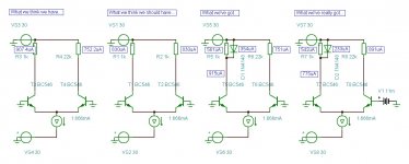
2. The balance of the currents in the input stage, or rather the allowed un-balance from the 22k resistor vs. 1k, and the kind of not properly set total current in the current source.
The balance of the current(s) in the input stage has been bugging me for while now.
But I think I'm getting it now. Thinking those 2 resistors should be the same is a thinko.
The 1k resistor always has 0.7volts (ish) across it because of TR4 and V=IR or some such rubbish and we know V and R
Anyhow see if this picture helps, I'm pretty close to concluding the 22k resistor isn't big enough...
No wait that's not it, the 22k resistor can be value you like. It's the resistor on the current source needs to limit the total current to twice the current of the first transistor... brb...
Attachments
Last edited:
The emitter currents of the LTP should be balanced.
where's the like button...
just spent most of the evening doing exactly that in simulations.
- Home
- Amplifiers
- Solid State
- NAP-140 Clone Amp Kit on eBay