Hello
Thanks for the advise Andrew.
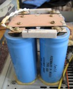
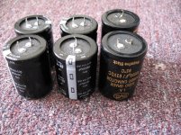
Here is my capacitors I used and I plan to use as a dual mono set up.
Andrew do you think is better to use C-R-C-R-C or just one R between the caps a la Pass F5?
I know that is a high power power supply since Class A amp.
I sow many people use only 2PC capacitor in their amplifier PS.
Even Jean Marc in his own amp, also if you look at the amplifier Nigel posted last time just 2PC capacitor only.
At the beginning (20 years a go) I did the same way but my friends told better to use min. 4 caps so I can make it CRC.
Any experience??
Greetings Gabor
Thanks for the advise Andrew.
Here is my capacitors I used and I plan to use as a dual mono set up.
Andrew do you think is better to use C-R-C-R-C or just one R between the caps a la Pass F5?
I know that is a high power power supply since Class A amp.
I sow many people use only 2PC capacitor in their amplifier PS.
Even Jean Marc in his own amp, also if you look at the amplifier Nigel posted last time just 2PC capacitor only.
At the beginning (20 years a go) I did the same way but my friends told better to use min. 4 caps so I can make it CRC.
Any experience??
Greetings Gabor
Attachments
Andrew , How do you feel about a capacitance multiplier to replace a resistor in a CRC filter ? . If adjusted carefully heat should be minimal . I could almost imagine the speed of the transistors to be unimportant if final C is large with usual decoupling near the power transistors . It is working to 1 kHz maximum I suspect ?
Capacitance Multiplier Power Supply Filter
Capacitance Multiplier Power Supply Filter
I did build a Cap Multi, a long time ago, to investigate how it worked. It was then that I discovered that adding a Zener+R alongside the last R of the string of RCRCRCR that you can get a two slope output voltage characteristic from the CM. The standard CM has a single slope ~ k*Vin
I never incorporated any CM into an amp nor pre-amp build.
I plan to try the Zenered CM in the F5x when I finally get it assembled.
I think a I posted an excel of the zenered CM a while back.
I never incorporated any CM into an amp nor pre-amp build.
I plan to try the Zenered CM in the F5x when I finally get it assembled.
I think a I posted an excel of the zenered CM a while back.
What an excellent suggestion . Usually it is a capacitor added to a zener as a noise filter . It sort of occurred to me something better was available form the same components , however I never got beyond thinking about it . My reluctance in using the zener is that it forces more heat out of the transistors if the voltage rises . I dare say you allowed for that ? Putting the zener on a climbing reference voltage might avoid that . It could be lets say a spare winding with 10000 uF and no great current used . That way a fixed relationship between zener and the job it is doing is maintained . The reference supply whilst of no sophistication will be nearly silent becasue no great current is flowing . It could also be CRC . No regulator as that defeats it's function .
CLCLC works well with this amp. I used 6800uf @ 63V and 10uH @ 5A. The way the earthing and return feeds are done are reckoned to be critical. I'm not that clever so I just followed the layout in the HackerCap thread on PFM
Rectifier/smoothing PCB for power amps - pink fish media
I use the same for my NCCs but the front end is CRCRC and regulated.
Rectifier/smoothing PCB for power amps - pink fish media
I use the same for my NCCs but the front end is CRCRC and regulated.
All Hitachi mosfet layout
Hello
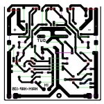
I did work on the all Hitachi mosfet amplifier layout. The Power stage and the driver stage almost done.
These way is very slow, I use the paint program to draw the layout. Need to think a lot all do I got used to it because most of my PC boards lay out was drawn like these.
To be serious I have no idea if those old JFet are replaceable with Toshiba J Fet..
I still wait on you guys Andrew or Nigel to open a new thread about these amplifier.
Two reason I wait, my English far from perfect and to explain in English electronics much more difficult than the every day English.
Nigel do you think that amplifier you would live to get a pair PC board the quality com parable with the NAIM??
I can each the boards but I just did a couple weeks a go so I must wait until I have enough work.
Before I desolder the parts from my old Naim PC board I will test the new PS set up.
I have to know can I count on the quality of these capacitors. Otherwise I will build a Stereo set up with 50V rail voltage.
Avondale advised that for 8 Ohms speakers as a max power supply voltage.
Greetings Gabor
Hello
I did work on the all Hitachi mosfet amplifier layout. The Power stage and the driver stage almost done.
These way is very slow, I use the paint program to draw the layout. Need to think a lot all do I got used to it because most of my PC boards lay out was drawn like these.
To be serious I have no idea if those old JFet are replaceable with Toshiba J Fet..
I still wait on you guys Andrew or Nigel to open a new thread about these amplifier.
Two reason I wait, my English far from perfect and to explain in English electronics much more difficult than the every day English.
Nigel do you think that amplifier you would live to get a pair PC board the quality com parable with the NAIM??
I can each the boards but I just did a couple weeks a go so I must wait until I have enough work.
Before I desolder the parts from my old Naim PC board I will test the new PS set up.
I have to know can I count on the quality of these capacitors. Otherwise I will build a Stereo set up with 50V rail voltage.
Avondale advised that for 8 Ohms speakers as a max power supply voltage.
Greetings Gabor
Attachments

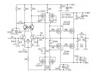
This is a doodle I did on The Hitachi design . It has 2 additions . A constant current source for the input pair ( 2 x 1N4148 , PNP transistor , 620R , 10 K ) . Provision for 2 x emitter resistors for the input pair . The lady I did it for had a friend helping her . The pictures were so as to help her discuss current mirrors etc . I retained the primitive Hitachi mirror as it works very well . Her friend changed that . If so 1 x 2SB716 is used as a diode as in more modern current mirrors . That is base to collector shorted . The PCB will do that if you prefer . To me that is a waste of a 2SB716 .
Note the equal resistance feedback arrangement from the MOSFET's , the output is taken exactly half way between them . It is good practice to do this . However because they are MOS FET's it is strictly speaking unimportant as they do not have equal output resistance . However it is still best practice to do it . At low level it will work so is worth doing . The original design didn't bother .
The top layer is just to make good use of the copper . The power wires should go direct to the TO3 transistors if possible . The cheaper TO3 P can be used ( plastic ) .
The input pair are close so as to get a good thermal match . The ground is a letter C shape . This is a bus-bar rather than Star . I take the input ground to the top of the C between 2 x 220 uF caps . I also return the Zoble circuit at that node ( my oscilloscopes says I should ) .
If a resistor is used in place of the constant current source and the emitter resistors replaced with links then the original Hitachi can be made from this PCB . Also a single VAS version as Naim if so desired . The current mirror converted into a Naim double constant current source would be easy . As said if someone gets as far as making some I would love a few . As far as I know the circuit is good to go with the PCB as shown . I suspect it is even correct size . Do check my top and bottom layers .
Hello Nigel
The attach. you posted not working (I can't enlarge the picture)
Now I have to ask you to post the schematic (how you like it or did modified) so I can see clearly. On the silk screen I see 6PC BJT.
The schematic you posted earlier I see less than 6PC.
I can make any one sided PC board, sometimes I have to some little mode if the copper traces to close to each other or to thin because I use the hot iron transfer method to transfer the ink in to the cooper. Not so good than the photo transfer. Also the red layout I'll have to rework (make it black). The size can be set up at the printer to the right size, that is not a problem.
Also it is possible to mod the lay out to the flat package power mosfet like 2SK1058/2SJ162.
I learned the best if the mosfet direct connected to the PC board. With out wires.
In case if we use wires must be hard wire and short as possible (still not as good like the mosfet soldered direct into the PC board).
The lay out I work on it is the all fet amplifier. I did go further but now I'll stop until I found out if I can get replacement for the JFets..
Did you heard the amplifier you posted in real life or just someone told you about or just run a sim?
I attach the circuit of the amp now I work on the layout just to avoid confusion.
The Source (5 or 10W power) resistors will go under the PC board.
I think I'll open a new thread for that amplifier, the best it would be if you or Andrew would do that.
You guys are perfect in English, I'm no where com pare my ESL weak English.
We could discus any of these circuit there let leave these thread to Naim (clone)only.
Greetings Gabor
Attachments
Last edited:
I tried that hot iron method . I did not succeed , well done . Yes I have listened to this version of the amplifier and I can say it is very free of any high frequency distortion . The specification graphs say so and my ears say I agree . Write to me in my in box and I will forward the diagrams if useful .
Sorry to anyone who wants more about Naim , always willing to talk about that .
Sorry to anyone who wants more about Naim , always willing to talk about that .
Ne tread was opened for the fet amplifier discussion
Hello
Here is the NEW thread for the mosfet amplifier.
You can post there your mosfet schematic, comment etc.
http://www.diyaudio.com/forums/soli...iy-designed-paul-kemble-naim.html#post3189232
Let s leave these thread to the Naim clone.
My English far from perfect, I hope I get help from you guys who already added to these amp.
Greetings Gabor
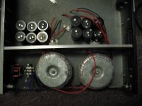
Hello
Some work done on the power supply.
I need to test the Sanken 2SC2922 device which was used originally in the Naim Chrome Bumper, of course with that need to be replaced the drivers to.
I read that was the best sounding from the Naim 140..
Also I want to test the Greg B mode..
AndrewT, Nigel I miss you at the new tread!!
We did some work thank to wahab.
I didn't knew even Marantz MA-24 has something common with Naim..
Greetings Gabor
Attachments
Slightly off topic, are there any ideas if this circuit would perform better as a fully complimentary output stage?
(...)
Naim also manage to preserve very nice instrumental tone, better than I have heard many amplifiers.
No, and if you think about it being quasi-complementary with matched transistors helps a lot. No N-P parts are truly complementary.
PS: Naim speakers are great, but they were underrated.
I need to test the Sanken 2SC2922 device which was used originally in the Naim Chrome Bumper
Hi Gabor, I'm waiting for this test
vs the OnSemi MJL recommended by McBride.Hello Teslar
The amplifier was tested many months a go and after the test I picked the best variation which is close to the NCC200..
We did tested the McBride design to and those semis he uses.
To me the NCC200 clone closer to my heart.
I will look up the layout for you, but since it was drawn by hand I do not have silkscreen..
As a reference you can use the McBride silkscreen because I took many of his idea when I made the layout.
Please let me know if you still interested on the layout, pm me direct to gaborzoltan2@gmail.com
Greetings Gabor
Hello
I would leave the McBride how is it. If is not a big deal to fabricate new PC boards I'll has the layout which include the Greg Ball mode to.
The Greg B mode was not tested yet but the orig NCC200 clone sound way better than the Ebay kit like day and night and much much better than the McBride clone.
Why I call it NCC clone. Because I made several mode.
I use flat pack power transistors, Elna Silmic caps only on the input I use BG non polar.
These amplifier need speaker protection, when you turn of the amp and the rail voltage fall until 7-8V the power transistors open up and let that 7-8V to go out to the speaker coil.
Otherwise the sound is awesome.
Tomorrow I will take out one side of the old (test amp) and I let you know the transistor set I use.
I spent long time until I matched the transistors to get the best sound.
How I stated earlier I want to rebuild the amp in that case I made picture from.
These amps sound good enough to be build..
Also I want to test the Greg B mode and the Sanken power transistors to.
If you go back 2 or 3 page you will see my PC board and some layout (that is not the latest, it does not have the Greg B mode) you can compare that layout with the McBride's layout.
I found the color coded layout but that does not have the option to implement the Greg's mode.
Tomorrow I will look up that to you if you interested to make your own PC boards..
Greetings Gabor
Attachments
ALL NPN
Douglas Self quoted Julian Vereker ( founder of Naim ) as saying NPN, PNP transistors are as truly matched as men and women of the same height and weight ( I wasn't there so it is how I understood he said it ) . If wanting to experiment be brave . For the output stage try complimentary feedback pairs ( CfbP ) . This will require a new bias arrangement . Part of the Naim is already a CfbP ( the NPN output collector connected to speakers ) . The other option is MOS FET . Exicon 10N/P 16 . If so the bias becomes a simple 470 R variable resistor . Also the Darlington/ CfbP drivers can be removed . On top of that the protection circuits are not really required with FET's . I doubt if the conventional Darlington NPN / PNP output stage is the best move . Naim like Harley Davidson had reason for what they do ( forgive the English , it allows for me not knowing about modern Naim ) . Any fool can see HD are wrong , funny how being wrong hasn't hurt them ! In all truth HD are more wrong than Naim ( i.e. 90 degrees V is better ) . People don't like the Naim circuit because it looks like a horrible compromise . I am told a debate went on for years about this in Wireless world . With some reluctance people had to accept Naim were right and they could justifiably state a feedback pair could perform exactly as an PNP or better . When PNP's caught up using all CfbP seems even better .
Douglas Self quoted Julian Vereker ( founder of Naim ) as saying NPN, PNP transistors are as truly matched as men and women of the same height and weight ( I wasn't there so it is how I understood he said it ) . If wanting to experiment be brave . For the output stage try complimentary feedback pairs ( CfbP ) . This will require a new bias arrangement . Part of the Naim is already a CfbP ( the NPN output collector connected to speakers ) . The other option is MOS FET . Exicon 10N/P 16 . If so the bias becomes a simple 470 R variable resistor . Also the Darlington/ CfbP drivers can be removed . On top of that the protection circuits are not really required with FET's . I doubt if the conventional Darlington NPN / PNP output stage is the best move . Naim like Harley Davidson had reason for what they do ( forgive the English , it allows for me not knowing about modern Naim ) . Any fool can see HD are wrong , funny how being wrong hasn't hurt them ! In all truth HD are more wrong than Naim ( i.e. 90 degrees V is better ) . People don't like the Naim circuit because it looks like a horrible compromise . I am told a debate went on for years about this in Wireless world . With some reluctance people had to accept Naim were right and they could justifiably state a feedback pair could perform exactly as an PNP or better . When PNP's caught up using all CfbP seems even better .
I found the color coded layout but that does not have the option to implement the Greg's mode.
Tomorrow I will look up that to you if you interested to make your own PC boards..
Greetings Gabor
Yes please, I know one guy that can etch a good pcb (and with silkscreen too that would help me not making mistakes
).I'm not in a hurry to build it, though, and it will be interesting to hear your opinion on Greg's mods.
- Home
- Amplifiers
- Solid State
- NAP-140 Clone Amp Kit on eBay