Hmm..the irony of trying to allow for fakes...that is sooooo depressing, Barry.
The Vre measurement at R29, I can't follow but seems low as you need about 30mA bias current flowing through tne output transistors.
With 0R22 resistors, that's ~6 mV across either emitter resistor..
The readings across the output terminals are just fine. They can be trimmed by the selection and match of the input transistors, beleve it or not. If there is no other offset adjustment on the PCB, this can be done later as a finishing touch.
Perhaps others would like to comment on the bias and my guess.
You may still have a problem but hey, it's ALIVE!")
The Vre measurement at R29, I can't follow but seems low as you need about 30mA bias current flowing through tne output transistors.
With 0R22 resistors, that's ~6 mV across either emitter resistor..
The readings across the output terminals are just fine. They can be trimmed by the selection and match of the input transistors, beleve it or not. If there is no other offset adjustment on the PCB, this can be done later as a finishing touch.
Perhaps others would like to comment on the bias and my guess.
You may still have a problem but hey, it's ALIVE!
Last edited:
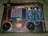
Ah yes, it is a Nac92, but it now incorporates dual regulated supplies and transformers. I hate Naim for leaving all that room in the box when it could have it's own supply. Hi Crispy. I had alot of problems to begin with. I'm not very techy, but it was well worth it in the end. There are 90 caps in the power supply. The idea being to get as much uF in a very slim case as I could. I used two transformers for the same reason. (They are not two separate supplies, just paralleled). The nap boards come from Tubeshunter on ebay. The case was an ebay bargain as it had a very blown-up amp in it originally. Barry
Polarity of feedback capacitor question
Most of the schematics I've seen for the NAP series and clones, and also the ncc200 show the positive of the feedback capacitor to be towards the 1k resistor side. However another one I have seen (http://www.neilmcbride.co.uk/output-amp2.pdf) shows the positive to be on the other (ie toward the ground or zero volts side).
My simulations shows that the zero volts side is always positive relative to the 1k resistor side. With a 1v input the voltage difference on between the capacitor terminals is around 90mv and current is around 1.2ma
So, is neil mcbride right and therefore are all the others wrong? Or given the small voltages and currents involved does it matter?
Polarities
We know that electrolytic capacitors need a charge potential of some level greater than around 2 volts to give lowest AC distortion. I read this as if the signal comes close to or crosses the zero charge potential, it may be noticeably affected by the electrochemical changes.
Electrolytics can be damaged by operating with reverse polarity, even though some applications clearly allow it but that may not be so bad for AC distortion, as long as it is not near zero or perhaps some empirically determined "worst case" DC potential.
The real issue is that we have an unsuitable component that like everything, is a compromise of cost and performance. In low noise amplifier designs, where the low impedance requires large feedback capacitance, there is no practical option short of Tantalums that can be cheaply applied. DIYs may rubbish Tantalums for good reasons but I take the view that if they are right for Naim, they are still right for their characteristic sound that put them "up there" in the first place.
I think it's worth considering that low distortion does not always equate to best perceived sound and we may simply be choosing a more pleasant one when we judge audio by ear. Consequently, good design principles are often ignored in some designs and this is probably the case here. So, it's not a question of right and wrong but which Audio Guru's rave appeals to you.
I think this is another "too difficult" issue.So, is neil mcbride right and therefore are all the others wrong? Or given the small voltages and currents involved does it matter?
We know that electrolytic capacitors need a charge potential of some level greater than around 2 volts to give lowest AC distortion. I read this as if the signal comes close to or crosses the zero charge potential, it may be noticeably affected by the electrochemical changes.
Electrolytics can be damaged by operating with reverse polarity, even though some applications clearly allow it but that may not be so bad for AC distortion, as long as it is not near zero or perhaps some empirically determined "worst case" DC potential.
The real issue is that we have an unsuitable component that like everything, is a compromise of cost and performance. In low noise amplifier designs, where the low impedance requires large feedback capacitance, there is no practical option short of Tantalums that can be cheaply applied. DIYs may rubbish Tantalums for good reasons but I take the view that if they are right for Naim, they are still right for their characteristic sound that put them "up there" in the first place.
I think it's worth considering that low distortion does not always equate to best perceived sound and we may simply be choosing a more pleasant one when we judge audio by ear. Consequently, good design principles are often ignored in some designs and this is probably the case here. So, it's not a question of right and wrong but which Audio Guru's rave appeals to you.
My interest in this issue of feedback capacitor polarity is a very basic practical one. With a polarised capacitor in circuit "the wrong way around", with higher voltages, after a short time, the internal insulator breaks down and often bubbles and smokes before the capacitor expires.
My simulations show the "negative to ground" to be the wrong way around" for the feedback cap yet that's the way most schematics show this. With higher voltages involved, this cap would expire quickly but with lower voltages it obviously doesn't but perhaps it degrades slowly.
So I wonder why is "the wrong way around" orientation for this capacitor continue to be the most poular one?
Polarities
Fair question, treated by both D.Self and Randy Slone. See Self's "Load invariant amplifier" design.
The feedback divider resistors limit current to the electrolytic so simple diodes can shunt current around it (be in parallel with it). Use 2 IN4148 or similar silicon diodes in series in both directions for a total of 4 x 1N4148. This limits the voltage to 1.3V DC in either polarity fault condition at the output.
You may simulate various potentials at the hot elecro, terminal but I've not noticed this in real life unless there was an offset fault. The DC reference node is the output, so place a load there and see what effect there is on that DC feedback . There are limited options where a small negative potential arises other than DC feedback but you can disconnect the output stage and simply drive the VAS into a 10k load with the feedback taken from there as the beginning of an experiment.
Edit: This may reflect input pair imbalance - others may wish to comment, as I don't currently do sims. You could try replacing input transistors to see how random the modelling is.
Last edited:
So I wonder why is "the wrong way around" orientation for this capacitor continue to be the most poular one?
Hi,
The orientation depends on the DC output component.
The maximum AC voltage across the feedback capacitor will never exceed something around + or -1Vac at full power.
If your real-life DC output component is positive attach the capacitor with negative to ground. If negative - vice versa. It's true that tantalums are more sensitive to reverse polarity, but don't sweat it too much, we are talking max. 1-4mVdc here.
Another option is non-polar capacitor, of course.
feedback capacitor polarity
It seems to me that the simplest way of envisaging capacitor polarity placement is for the +ive terminal to always be kept at a higher voltage than the -ive terminal.
Thanks to Ruwe for motivating me to actually measure the feedback capacitor voltages on my ncc200. The readings (relative to ground) on the side going to earth [the negative side] were (initially around -70mv) quickly falling to around -40mv) while the positive side was close to zero at around -0.4mv. So basically the various schematics do show the caps to be "the right way around".
Feedback capacitor confusion
I'm really puzzled now. After measuring the voltages I concluded that the ncc200 schematic (and those of the various clones) showed the cap to be "the right way around" ie with the -ive towards earth and the +ive towards the 1k resistor.
Now I'm no longer sure about this.
When I was doing the measurements I used the plus signs on the caps and on the pcb as my reference points and assumed they were consistent with the schematic.
But after looking closely at the board I find the schematic and pcb to be inconsistent. On the ncc200 avondale board the +ive on the pcb overlay and the associated track is towards earth and not towards the 1k resistor. So on my voltage measurements the schematic is wrong and the pcb orientation of the cap (+ive to earth) appears to be correct. My simulations, which previously I thought were incorrect, also support the +ive to earth orientation.
So I'm puzzled.
It seems to me that the simplest way of envisaging capacitor polarity placement is for the +ive terminal to always be kept at a higher voltage than the -ive terminal.
Thanks to Ruwe for motivating me to actually measure the feedback capacitor voltages on my ncc200. The readings (relative to ground) on the side going to earth [the negative side] were (initially around -70mv) quickly falling to around -40mv) while the positive side was close to zero at around -0.4mv. So basically the various schematics do show the caps to be "the right way around".
I'm really puzzled now. After measuring the voltages I concluded that the ncc200 schematic (and those of the various clones) showed the cap to be "the right way around" ie with the -ive towards earth and the +ive towards the 1k resistor.
Now I'm no longer sure about this.
When I was doing the measurements I used the plus signs on the caps and on the pcb as my reference points and assumed they were consistent with the schematic.
But after looking closely at the board I find the schematic and pcb to be inconsistent. On the ncc200 avondale board the +ive on the pcb overlay and the associated track is towards earth and not towards the 1k resistor. So on my voltage measurements the schematic is wrong and the pcb orientation of the cap (+ive to earth) appears to be correct. My simulations, which previously I thought were incorrect, also support the +ive to earth orientation.
So I'm puzzled.
I can only write a translator from Google. Capacitor VISHAY BC 68mkF-6,3V has been working for about seven years, with a voltage of opposite polarity around-14mV. It works without any problems so far. The sound amplifier is very good.
With best regards and Happy New Year, Nikolay. St. Petersburg
With best regards and Happy New Year, Nikolay. St. Petersburg
Every conventional amplifier on this forum has the same issue but it does not concern us that the feedback electro. has a tiny and variable reverse charge.
The advice you are getting here is that it's inconsequential as it will vary from build to build and over time, which polarity and actual voltage you read on your DMM.
However, if you must have it notionally correct, then follow Martin Clark's suggestion and reverse it to suit the way your individual unit has settled. That will be how Avondale have intended it and other fastidious manufacturers too. The schematic polarity is conventionally + to the signal end but it's quite arbitrary and means absolutely nothing with real amplifiers.
As Ruwe has said "don't sweat it". It is an aesthetic consideration and you'll never boil or significantly reduce the life of any electrolytic at the impedance levels and voltages you are worried about.
The only way to alter the DC feedback voltage (which is what you are measuring at the base of Q2 via a 1k resistor) is to change the current balance between the input pair transistors, also affecting offset voltage and the design input stage operating conditions. Sometimes, merely selecting a better matched input pair (Hfe & Vbe) will change that offset sufficiently and the "sound" will change too.
Hi meanmanPlanning to make a new layout of the NAP140 and NCC200.Who can provide me the latest schematic and suggestions regarding the best output and pre driver trannies etc.
You would have something close already with your DX blame ST. Just kick the bootstrap VAS and use a Current Source - Voila! Naim circuit, any type!
Here is a link to Avondale's site on the NCC200 page and you will find the NAP 140 posted here on page 67 #668. Of course, you will need to know that the clones this thread discusses all have the VI limiter circuit removed. We could go through all the details but a glance at the Avondale schematic will show you exactly what needs to be deleted from the NAP 140. Needless to say - VI limiters save burning output stages but they can affect sound at high level.
DIY Audio Power Amplifier modules : DIY Audio
You will find transistors discussed here several times over. The question is, what you expect. Naim or something else for the sound quality. They affect your choices,
Last edited:
- Home
- Amplifiers
- Solid State
- NAP-140 Clone Amp Kit on eBay