HI
My amplifier with my modification it work from the first time .
I don't know why they talk about oscillation I did not had that experience never . I used a very cheap cable or I used Kimber 8TC speaker cable and no oscillation at all . IT IS A GREAT AMPLIFIER and it has the possibility even to do further improvement . For ex. the Elna Slimic not the best sounding capacitor .Much better to use Elna Cerafine or if you can afford it BG capacitors . Some one replaced the Slimic capacitors with Panasonic FC series and he wrote the sound of the amp get much better .
Probably some fake Toshiba transistor blew up??!
I only had problem with the further improved board some of the ground had no connection at all with the input ground .
I think the guy fix that problem on the new PC boards .
There is two guy on the Ebay who sell Naim Clone , I would prefer the blue PC board , the further improved Naim Clone .
That guy did a very good job and he did a lot of test on the amp .
The another kit I can't comment since I never had one .
But I can see the two kit has some different parts on it .or some pars missing from the smaller board .
Just take a look the emitter resistors , the one has 3PC the another only 2PC .
For me it really has no reason to support one seller and not the another .
Both guy is very helpful and I purchase parts from both guy .
Greetings
Hi,
Hoka, you're right. You can't hear most of the oscillations because they tend to be above the range that we are able to hear. So, without a scope it will be not possible.
On the other hand, when my amp was oscillating, it created very unpleasant distortion in high frequencies - my tweeter sounded like a non-tuned radio station. I was lucky that it was so severe that it was audible. Sometimes it can be there but still not enough audible in the speakers. Then your amp will run hotter (or not, I've only read about this possibility), and you'll still have negative effect on the sound.
Eventually, the oscillation frequency modulates with other frequencies and creates harmonics. Who knows what harmonics and how strong they would be in any particular case?! Some of them may be in the audio band and some of them may be strong enough to be heard, as mine. Or they can only change the balance of the amp, making it to sound dull, or harsh, or chesty ... unnatural of any kind. My friend uses the best scope that any of us have – his own brain") He says: “If a feel tired and I have headache after 1 hour of listening to an amp, there is a problem”. I would add, if you tend to stop listening to music, or you tend to turn the volume down and not up – something's wrong.
He says: “If a feel tired and I have headache after 1 hour of listening to an amp, there is a problem”. I would add, if you tend to stop listening to music, or you tend to turn the volume down and not up – something's wrong.
My oscillating DIY speaker cable is CAT5 – 25 pairs (used as backbone cable in telecomm). I had each pair split - one going to positive, and one to negative. Unfortunately, this way I've created very high capacitance (the inductance is something that is almost constant in any cable) and the amp was unstable. I use now two short pieces of QED Silver Anniversary and the amp is OK.
QED have published the cable specs on their site. According to my calculations this cable is about 100 ohms characteristic impedance (still low for a Naim). QED say 43pF/m and I measured my DIY cable to be as much as 3.6nF for a length of 2 metres – what a difference!!!
BTW, a standard CAT5 – 4 pairs has same parameters as the QED if you use one whole cable for positive and one for negative, but you keep them together into a heat shrink, for example. I don't know how the capacitance would be if they are separated by some sort of spacers in between – I'm not so eager to experiment with cables.
Bottom line, the Naim cable is very low capacitive. I don't know how they've made it 20pF/m. And the amp likes it this way. Note, my amp has a coil at the output and was still oscillating with my very wrong DIY version. Also, IMO the amp needs some minimum resistance in the output path, that's why they recommend min. lengths.
In the Vereker's post he mentions the NACA4 parameters, which is very useful information, provided that Naim don't give technical specs on their electronics. I remeber the time when they didn't mention even the power ratings of their amps ... They've melted a bit since then
Greetings
P.S. I agree that the value and the type of the feedback capacitor is affecting very much the sound. Experiments are in order
Hoka, you're right. You can't hear most of the oscillations because they tend to be above the range that we are able to hear. So, without a scope it will be not possible.
On the other hand, when my amp was oscillating, it created very unpleasant distortion in high frequencies - my tweeter sounded like a non-tuned radio station. I was lucky that it was so severe that it was audible. Sometimes it can be there but still not enough audible in the speakers. Then your amp will run hotter (or not, I've only read about this possibility), and you'll still have negative effect on the sound.
Eventually, the oscillation frequency modulates with other frequencies and creates harmonics. Who knows what harmonics and how strong they would be in any particular case?! Some of them may be in the audio band and some of them may be strong enough to be heard, as mine. Or they can only change the balance of the amp, making it to sound dull, or harsh, or chesty ... unnatural of any kind. My friend uses the best scope that any of us have – his own brain
He says: “If a feel tired and I have headache after 1 hour of listening to an amp, there is a problem”. I would add, if you tend to stop listening to music, or you tend to turn the volume down and not up – something's wrong.My oscillating DIY speaker cable is CAT5 – 25 pairs (used as backbone cable in telecomm). I had each pair split - one going to positive, and one to negative. Unfortunately, this way I've created very high capacitance (the inductance is something that is almost constant in any cable) and the amp was unstable. I use now two short pieces of QED Silver Anniversary and the amp is OK.
QED have published the cable specs on their site. According to my calculations this cable is about 100 ohms characteristic impedance (still low for a Naim). QED say 43pF/m and I measured my DIY cable to be as much as 3.6nF for a length of 2 metres – what a difference!!!
BTW, a standard CAT5 – 4 pairs has same parameters as the QED if you use one whole cable for positive and one for negative, but you keep them together into a heat shrink, for example. I don't know how the capacitance would be if they are separated by some sort of spacers in between – I'm not so eager to experiment with cables.
Bottom line, the Naim cable is very low capacitive. I don't know how they've made it 20pF/m. And the amp likes it this way. Note, my amp has a coil at the output and was still oscillating with my very wrong DIY version. Also, IMO the amp needs some minimum resistance in the output path, that's why they recommend min. lengths.
In the Vereker's post he mentions the NACA4 parameters, which is very useful information, provided that Naim don't give technical specs on their electronics. I remeber the time when they didn't mention even the power ratings of their amps ... They've melted a bit since then
Greetings
P.S. I agree that the value and the type of the feedback capacitor is affecting very much the sound. Experiments are in order
How do you determine if there is an oscillation?
from Unclejed613
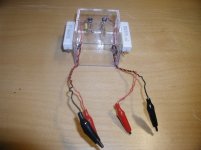
"you might want to try a "quick and dirty" oscillation detector using an LED. you want to take an LED, put a 100 ohm resistor in series with it, then put a 4.7nf cap in series with the 100 ohm resistor. the "unused" leg of the LED becomes ground (polarity of the LED doesn't matter). the open leg of the cap becomes the input. then put a 1k resistor from the junction of the cap and series resistor to ground. the circuit is connected across the speaker terminals. any oscillation above 1 volt and above 20khz should light the LED, especially if the oscillation is continuous."
I built one and it works great for me. Attached is a pic. I check DC offset and for oscillation before ever attaching a pair of speakers to an amp..
The white resistors on the outside are the 4 ohm or 8 ohm dummy speaker loads. This way I don't have to attach the speaker terminals to the amp being tested...
Don't know if it would detect any and all oscillations...
Attachments
Thats a very good idea by unclejed, simple and I think it would work pretty well. Actually its awesome for diyers that dont have resources for scopes.
Ruwe, good input, now many builders here can sort out a problem I think most of them have. This is a quite a good sounding amp when its operating properly. Strange why nobody mentioned the oscilating problems without the use of some peculiar cables before, Julian Vereker certainly had a peculiar way of doing things.
Its better to test with a speaker load, or rather with a dummy load at first but with some capacitance. A purely resistive load is not of much use and does not represent a accurate speaker load.
Yes, interesting small indicator circuit. Can be helpful if the oscillation is constant and not just a very short spike.
I totally agree with Homemodder, that pure resistance is not a realistic load and will not cause oscillations if we assume that the amp circuit is properly designed. I think that this amp is generally simple to build and to make work, but it's part of the whole Naim system, and it needs the right front and end to make it perform at its best.
I'm curious to know more about how it sounds in your systems, compared to other designs, guys.
Hi,
I've had mine built for a while now (DC offset on both is below 6mV) , working great with BC550C in Q5, but I decided to replace it with TIP41C as per reccomendations and mount on the heatsink (noting the different pins).
Now both boards exhibit the same problem:
- distored sound
- R33 gets very hot and discoloured
- After about 30s the 2A fuses in the + supply lines blow.
The only thing I can think of is I am using 50V supply lines, but like I say it worked great before!
One must remember that when using the TIP transistor as Q5 in the way you describe, it ought to be electrically isolated from the heatsink, in the same way as the output tranistors. Probably needless to say, but one never knows...
You could also use the BC550 in the same way I suppose, just gluing it to the heatsink, keeping the layer of glue very thin. Eventually cover it with something in addition (anything) to keep it warm. Good luck.
You could also use the BC550 in the same way I suppose, just gluing it to the heatsink, keeping the layer of glue very thin. Eventually cover it with something in addition (anything) to keep it warm. Good luck.
Hi df_genius,
First, I would put back the BC550 to see if it fixes the problem...
By R33, do you mean the resistor 4.7k in the protection circuit? Very weird.
To me it looks that you have blown one of the output transistors, or one of their drivers - most likely Q10 or Q12 side. When you change Q5 you have to take care that the trim. pot is turned max CCW. BC550 and TIP41 have different base-emitter parameters and will provide different bias current to the output transistors for the same trim. pot settings. With TIP41C, the provided current had been too high and eventually had blown your output.
I suppose that the distortion that you hear is the amp working on half-sine wave output only.
Check the voltage across R29, R30. If it's unusually high and the drop across both resistors is not equal, this would be one more indication of blown output transistor/s.
Hope this may help.
Regards
John,
Maggies are rugged as hell. Only high spls over long periods will ruin them in my experience - glue separates - and you know the only problem is not that they are difficult to drive at all, but simply that all that wire acts as a very good radio antenna! A 3.3nF cap at the inputs shorts out any RF.
They have zero phase shift, Maggies, in sharp contrast to other drivers, and this makes them an ideal choice for a global negative feedback amplifier.
Hugh
Naim PC boards and Sanken power transistors for sale
Hello
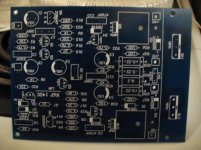
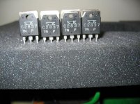
I have pair extra Naim 140 Clone PC board for sale with 4PC matched (original) Sanken 2SC2837 power transistors .
I will include the part list and the schematic of course .
I ask for these $35 .
These is a brand new professional made PC boards . The 4 Sanken cost at least half of the asked price and if you want to get matched transistors you have to purchase 15-20PC .That would cost you more than how much I ask for these set.
I know on the Ebay available as a kit but half of that kit you have to replaced .Better resistors min.Dale , the Toshiba power transistors are probably .... you can read at the ESP site .Even someone wrote on the forum he needed to replace the Elna Silmic ll capacitors because the sound was lifeless .
What I want to say if you build up the Kit U use what ever you think is the best !
Greetings
Hello
I have pair extra Naim 140 Clone PC board for sale with 4PC matched (original) Sanken 2SC2837 power transistors .
I will include the part list and the schematic of course .
I ask for these $35 .
These is a brand new professional made PC boards . The 4 Sanken cost at least half of the asked price and if you want to get matched transistors you have to purchase 15-20PC .That would cost you more than how much I ask for these set.
I know on the Ebay available as a kit but half of that kit you have to replaced .Better resistors min.Dale , the Toshiba power transistors are probably .... you can read at the ESP site .Even someone wrote on the forum he needed to replace the Elna Silmic ll capacitors because the sound was lifeless .
What I want to say if you build up the Kit U use what ever you think is the best !
Greetings
Attachments
- Home
- Amplifiers
- Solid State
- NAP-140 Clone Amp Kit on eBay