Oh, HICAP clone is exactly the same circuitry with the exception of TO-3 packaged LM317 plus high power transformer.
It is easy to clone the appearance.
However, to achieve the same performance, the transformer, as well as the wiring and the socket, is the key.
Did you have chance to look at the wire used in the transformer ?
I am still curious about it.
Yes I checked and the wires are silver colored so probably aluminum.
The windings however, I don't know. You'll need to open it up.
Ok thank you very much.Full rail voltage on the speakers terminal , very likely one of the power device is dead open. Make sure when ever you adjust or set up your amplifier you do not connect your $$$ speakers to that amp. Use something cheap even a raw driver would do the job for that.
Start measuring you power devices,")
Any suggestions which ones first?
All TR11 and TR12 are open.
That means something downstream had damaged it.
Need to test the other transistors too.
***edit I checked again, tested the probes on wrong pins. They check out. So +ve probe is at B, and -ve is E and C, they all check out ok with Diode testing.
That means something downstream had damaged it.
Need to test the other transistors too.
***edit I checked again, tested the probes on wrong pins. They check out. So +ve probe is at B, and -ve is E and C, they all check out ok with Diode testing.
Last edited:
Re : Transformer
Appreciated your feed back.
It seems I need to find EI transformer for my needs.
To protect your expensive power transistor, for this type circuit only, you can get 4 diode between base and emitter and remove the power transistor. Let Collector float.
The last stage is only current gain. Without current amplification, voltage value will hold.
It can not drive low impedance such as speaker but has no issue driving your volt meter.
The reason you need forward biasing diode is to complete the feedback loop.
At this time, check all voltage reading. If output point is wrong. find the issue.
If output is 0V DC, apply small sine wave (or simply using your finger), you should see AC output reading.
When adjust the trim, you can see DC voltage change on diode. Set to lowest before replacing the real transistor.
I did not witness what happened. It could be faulty circuit or simply a thermal issue. Internal P-N junction could overheat very quick before observed on the package surface.
1N4001 or 4148, any silicon diode will do.
Digital diode test is not very accurate. The current is too low.
You should take power transistor out of the board and at least using analog meter for higher current testing.
e.g. with analog meter at K ohms range, if C-E (or B-C/B-E reversed biasd) has a reading (needle moves) rather than infinite, this transistor maybe defective.
Multi meter at most apply few volts to test the semiconductor.
So if leakage occur at low voltage, it may imply a short with 40V bias (as example).
All TR11 and TR12 are open.
That means something downstream had damaged it.
Need to test the other transistors too.
***edit I checked again, tested the probes on wrong pins. They check out. So +ve probe is at B, and -ve is E and C, they all check out ok with Diode testing.
Appreciated your feed back.
It seems I need to find EI transformer for my needs.
To protect your expensive power transistor, for this type circuit only, you can get 4 diode between base and emitter and remove the power transistor. Let Collector float.
The last stage is only current gain. Without current amplification, voltage value will hold.
It can not drive low impedance such as speaker but has no issue driving your volt meter.
The reason you need forward biasing diode is to complete the feedback loop.
At this time, check all voltage reading. If output point is wrong. find the issue.
If output is 0V DC, apply small sine wave (or simply using your finger), you should see AC output reading.
When adjust the trim, you can see DC voltage change on diode. Set to lowest before replacing the real transistor.
I did not witness what happened. It could be faulty circuit or simply a thermal issue. Internal P-N junction could overheat very quick before observed on the package surface.
1N4001 or 4148, any silicon diode will do.
Digital diode test is not very accurate. The current is too low.
You should take power transistor out of the board and at least using analog meter for higher current testing.
e.g. with analog meter at K ohms range, if C-E (or B-C/B-E reversed biasd) has a reading (needle moves) rather than infinite, this transistor maybe defective.
Multi meter at most apply few volts to test the semiconductor.
So if leakage occur at low voltage, it may imply a short with 40V bias (as example).
Last edited:
All TR11 and TR12 are open.
That means something downstream had damaged it.
Need to test the other transistors too.
***edit I checked again, tested the probes on wrong pins. They check out. So +ve probe is at B, and -ve is E and C, they all check out ok with Diode testing.
What most people usually find is that the supplied transistors don't match the board layout. I would check that first. Another indication pointing to the layout is that both channels are like that. It doesn't have to be the output devices. There are many other conditions that may give positive or negative full DC output.
If the layout checks out, then you really have a problem and you'll need to go trough the exercise of measuring the voltage in every node of the circuit with reference to ground. Then post here and we'll think together. Many people here will be able to help.
At power up you can use a simple light bulb soft starter..
These would help to avoid damages like these
Are the power transistors original or Ebay stuff. Last time I used Sanken it blew up into my face at DoGC amp.
Which is line & which is neutral?
Why the radio?
Why the radio?
It's so you'll still have music even if the amplifier is bad.
Which is line & which is neutral?
Why the radio?
Bulb goes to the power line.
Radio and all the rest just an illustration.
Please use a regular 100W light bulb.
When something wrong the light bulb powers up all the way...What most people usually find is that the supplied transistors don't match the board layout. I would check that first. Another indication pointing to the layout is that both channels are like that. It doesn't have to be the output devices. There are many other conditions that may give positive or negative full DC output.
If the layout checks out, then you really have a problem and you'll need to go trough the exercise of measuring the voltage in every node of the circuit with reference to ground. Then post here and we'll think together. Many people here will be able to help.
I've gone through the datasheet for the transistors and they all check out comparing their legs and the schematics. I'll need to check the voltages on all the nodes yes. Yesterday I checked even at the inputs after the 10uF input cap there's already 24+V DC. Several other test points also show up to 35-40VDC.
In the schematic by Algar, TR1 and TR2 are written as HFE 500/430 respectively. If I had matched them instead of following this value, could this be it too?
At power up you can use a simple light bulb soft starter..
These would help to avoid damages like these
Are the power transistors original or Ebay stuff. Last time I used Sanken it blew up into my face at DoGC amp.
The 2922 are supplied with the kit and confirmed fakes, but they work fine and has been working before I changed the components.
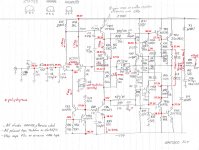
29V at the emitters of the input pair cannot be right.
have you inserted the transistors correctly?
have you used NPN pair?
Goodness, one look and you figured it out. I used a pair of BC550 and the pins are reversed 123. Everything now reads within a few mV from the Algar schematics.
Wow this is amazing. Truly.
Goodness, one look and you figured it out. I used a pair of BC550 and the pins are reversed 123. Everything now reads within a few mV from the Algar schematics.
Wow this is amazing. Truly.
Well I spoke too soon.
The circuit and everything is good, but because I've been flipping the board back and forth too many times transformer input 0V got disconnected and both R12-13 burned. Transformer sounded like it sizzled too. Saw some orange spots from inside the plastic wrap. Must be the enamel on the copper wires burning off.
However, the TR1,TR2 were the problem and rectified.
Member
Joined 2009
Paid Member
Goodness, one look and you figured it out.

I'm also building one and there the bc239 and bc550 has the same leg configuration.
Or you were comparing to the ztx and mps ones?
I'm not sure what was my original TR1 and TR2 (the board is written MPSA18), but now the BC550 are backwards compared to the stencil on the board. Ie: Instead of 1,2,3 the pins are 3,2,1.
Last edited:
I'm not sure what was my original TR1 and TR2 (the board is written MPSA18), but now the BC550 are backwards compared to the stencil on the board. Ie: Instead of 1,2,3 the pins are 3,2,1.
That's the usual issue with these kits. The layout was made for certain transistors, but you receive different with the kit. Always check they match the board! BCxxx are European (Philips) and MPSAs are American style. And you're right, they are exactly in reverse.
I'm not sure what was my original TR1 and TR2 (the board is written MPSA18), but now the BC550 are backwards compared to the stencil on the board. Ie: Instead of 1,2,3 the pins are 3,2,1.
I thought you had the schematic like the in the measurement picture.
MPS ones are backwards. Then all clear.
I also checked the pcb how the transistor should fit in, not to mix up legs.
I'll fit in bd139/140 instead of the ztx for first test as I didn't have it in local shops. There I had to bend the legs around to be able to fit it in.
The shematic was from Algar, assuming he's using equivalent components the measurement points and values should still be the same.
- Home
- Amplifiers
- Solid State
- NAP-140 Clone Amp Kit on eBay