Again, looks like a quality kit from Caowei. I guess an issue here is that by the time the kit has been obtained, and a suitable transformer and chassis sourced and built then there won't be much difference in cost between the finished unit and a genuine 2nd-hand NAP 140.
For example, one here went for £150:
Naim Audio NAP 140 Power Amplifier | eBay
In this case I'd personally go for the genuine NAP 140 due to the minimal cost saving involved. For me the NAP 200 was an exception because of the price that even 2nd-hand examples command.
I guess it depends on the individuals' motivation for building their own units.
Chris
Second hand Naim power amps are hard to find here in the US at good prices, at least that is my experience. I could buy one from UK but probably need a step-down transformer which will add to cost (in addition to shipping from UK). Cost of the kit (Caowei NAP200) so far is around $260 without the transformer.
al
It's also expensive anywhere to have a single transformer wound to your spec. so I think the ability to use an off-the-shelf 25-0 + 25-0 V transformer of around 250VA will come as a relief, if you're worried about total costs for a NAP140 clone build. The shoebox case size should prove a lot cheaper and easier to prepare so things look good in a price comparison unless of course, you live in the UK and are confident at winning auctions and certain of the true condition of the amp, as I guess Chris would be.
It's also expensive anywhere to have a single transformer wound to your spec. so I think the ability to use an off-the-shelf 25-0 + 25-0 V transformer of around 250VA will come as a relief, if you're worried about total costs for a NAP140 clone build. The shoebox case size should prove a lot cheaper and easier to prepare so things look good in a price comparison unless of course, you live in the UK and are confident at winning auctions and certain of the true condition of the amp, as I guess Chris would be.
Of course it's buyer beware, but in my experience many listings have a serial number displayed - a quick email to Naim is all that is required to check service history to gauge how an amp has been treated. In any event a non-working genuine amp is arguably a better starting point than a clone.
EBay's global shipping programme significantly reduces the cost of shipping larger items overseas so shipping to many destinations is a non-issue assuming that the seller offers the option. There are usually plenty of 140s listed so it's not a big deal to miss out on a specific item unless it's particularly desirable for some reason.
If I understand correctly NAP200 clone (and original) uses a dual channel power supply, as a mono block configuration, in a single board (2X 28-0-28) whereas a stereo NAP140 clone shares a single 25-0-25 (or 28-0-28) supply even though factory NAP140 used a dual supply (2x 28-0-28 or 4x0-28). Why can't we use a single 28-0-28 in a NAP200?It's also expensive anywhere to have a single transformer wound to your spec. so I think the ability to use an off-the-shelf 25-0 + 25-0 V transformer of around 250VA will come as a relief, if you're worried about total costs for a NAP140 clone build. The shoebox case size should prove a lot cheaper and easier to prepare so things look good in a price comparison unless of course, you live in the UK and are confident at winning auctions and certain of the true condition of the amp, as I guess Chris would be.
NAP140 clone shares a single 25-0-25
You sure its with center tap ? Two bridge rectifiers does not make sense in a 25 - 0 - 25 configuration to me...
I tought it was 25-0 and 25-0.
You sure its with center tap ? Two bridge rectifiers does not make sense in a 25 - 0 - 25 configuration to me...
I tought it was 25-0 and 25-0.
If you study many of the images of genuine NAP 140 internals you will see that the transformer has what looks like a secondary winding with centre tap.
There's a bridge rectifier (and pair of smoothing caps) for each of the two channels - both rectifiers are being fed from the same secondary winding.
The wire colours from the secondary winding appear to be yellow, grey and green, with green being the centre tap.
Here's an example image: http://picdb.thaimisc.com/u/usedlism/8629-7.jpg
I'm away from home at the moment, but when I'm back at the weekend I'll test the noise level of my unit that has been in use now for about a month and is in a suitable enclosure etc...
Chris
For the NAP 200 clone I'm getting 0.0mV AC at the speaker outputs, read on a multimeter set to its 200mV range. This is the same for both channels with the inputs shorted to 0V.
A quote from Martin Clark/Acoustica.org.uk: NAP 140. 45W into 8 ohms. About 200VA transformer, 1 winding feeding 4x4,700uf caps running at about 34V rails if I remember.....
If you don't have a centre-tapped secondary, connect the two 25V windings in series and presto, one centre-tapped 50V winding, taking care that the "sense" or rotational direction of the windings is correct for series connection, according to the manufacturer's connection guide, otherwise you get no output at all and maybe a lot of heat and smoke. Use a bulb limiter for safety when powering up, if in doubt.
The board could be wired for dual mono operation as in the alternative arrangements shown in the Ebay pics and the NAP200 already discussed but that needs another special dual CT 50V or 4 x 25V winding transformer. The PSU board could have been designed for more than one model so don't assume it must be wired as a dual mono to work as the NAP140 was designed. (single winding, dual rectifiers and caps.)
Yes, but then two rectifiers are in parallel right, also as Filter caps? .. One psu for each amp. board.Use a bulb limiter for safety when powering up, if in doubt.
Found a device, some old smoked regulator which have lots of BC182B transistors in it. They are very close match to BC237 series
 Each has HFE about 300. Tried them on my own Naim clone PCB, they were good.
EDIT: they are really good(Y)
Soon i will receive VAS ZTX753 and 653 transistors. Drivers and CSS are MJE and MPSA as in original.
For outputs Toshibas will be replaced with "HI-END" 2N3055, they are from the same old regulator... produced in Hungary.... some say they can handle more then +/-30V.. will be trying +/- 41V anyways.
Few problems occured with BIAS 2N5551 transistor on naim. First, i can't set the bias below 1mV(emitter resistor) when the pot is turned all the way down.
Second, whole 1 channel amplifier board takes 19.98mA when 1mV is present on emitter resistor. It means output is taking 4.25mA and 15.73mA is going into VAS and LPT ????
EDIT: And one more case, when speaker is connected to amp output, voltage on emitter resistor rise from 5.2mV to 5.5mV, no matter what bias is set, voltage always rises by 0.3mV and stay's stable.
Laboratory +/- 30V supply.
EDIT2: on normal listening, the voltage drop on emitter resistor is set always to 5.5V, i meant 5.5mV, sorry
Last edited:
Hi rensli
No need to use craptanium parts like 2N3055 when there are good, cheap and suitable parts like 2SC5200, NJW3281 around. KEC 2SD1047 (K branded) are also good and cheap as well as some cheaper Sanken MT200 and TOP3 types. I found only slight differences between genuine output transistors but the sound quality from higher frequency, better linearity types did seem to be cleaner when substituted directly for 20 years old MJ15003, for example.
The voltage across the emitter resistors of TR3 and TR6 can be used to calculate the current in the input and voltage amplifier stages. Have a look at those values first, since I think the currents should not be more than 1.5 mA through TR3 and maybe 10 mA through TR6 but your parts and supply voltages have changed and you are off the clone path so it's difficult to know what you have there now and what to expect as the outcome. Perhaps you should simulate your changes first to check for correlation with actual measurements. Otherwise, you'll be lost in incorrect operation, such as a bias currents running too high. Post the relevant schematic, parts values and relevant voltages if you can.
Last edited:
Hey,
I apologize, should have calculated current on both resistors.
19.98mA - 2x 4.25mA = 11.48mA, more realistic.
Removed completely VI limiter from NAP250 circuit.
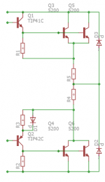
Then, installed ZTX753 VAS and ZTX653. MPSA06 in CSS and LPT is formed with BC182B transfer resistors. TIP41C series as drivers and TOSHIBA 2x 2SC5200 @ output.
None of the resistor or capacitor value is changed or added except MPSA06 emitter resistor which is 560R atm and 2SC5200 47nF+10uF decoupling capacitors. Offset is ~1.1mV
When ZTX series took place, magic happened(changed 56pF to 39pF), everything @music became so interesting. Never heard a mono speaker playing so nicely.
Amp is bright, very very tight and lots of details, i don't have words to describe this situation. NAP circuit should become more juicy, more mid and less bright with MJE253 as drivers. Will do it when H-140 are taken out from the AMP case
Technically, it became much more stable then it was(H-140 clone, with mods or not, doesn't really matter). Nasty tones like in 1K-3Khz range are much much softer to ear. I just don't have headache's by listening to mono.
Lets hope that stereo with 1 transformer center-tap winding will be as good as it is right now .
Didn't want to ruin the party by adding VI limiter back into NAP circuit. So, i have decided to add more output transistors in parallel. Is it possible while keeping naim concept ?
Right now, toshibas are paralleled without emitter resistors for current matching. I have tried lots of different techniques (with emitter/collector resistors) but sound is immediately worse, boring or god knows what else.
This is the configuration i stopped on, gives best results compared to previous parallel configurations:
I apologize, should have calculated current on both resistors.
19.98mA - 2x 4.25mA = 11.48mA, more realistic.
Removed completely VI limiter from NAP250 circuit.
Then, installed ZTX753 VAS and ZTX653. MPSA06 in CSS and LPT is formed with BC182B transfer resistors. TIP41C series as drivers and TOSHIBA 2x 2SC5200 @ output.
None of the resistor or capacitor value is changed or added except MPSA06 emitter resistor which is 560R atm and 2SC5200 47nF+10uF decoupling capacitors. Offset is ~1.1mV
When ZTX series took place, magic happened(changed 56pF to 39pF), everything @music became so interesting. Never heard a mono speaker playing so nicely
.Amp is bright, very very tight and lots of details, i don't have words to describe this situation. NAP circuit should become more juicy, more mid and less bright with MJE253 as drivers. Will do it when H-140 are taken out from the AMP case
Technically, it became much more stable then it was(H-140 clone, with mods or not, doesn't really matter). Nasty tones like in 1K-3Khz range are much much softer to ear. I just don't have headache's by listening to mono.
Lets hope that stereo with 1 transformer center-tap winding will be as good as it is right now
.Didn't want to ruin the party by adding VI limiter back into NAP circuit. So, i have decided to add more output transistors in parallel. Is it possible while keeping naim concept ?
Right now, toshibas are paralleled without emitter resistors for current matching. I have tried lots of different techniques (with emitter/collector resistors) but sound is immediately worse, boring or god knows what else.
This is the configuration i stopped on, gives best results compared to previous parallel configurations:
Attachments
Last edited:
Paralleled output transistors without emitter resistors is a dangerous game to play.
Andrew, do you have some advice to parallel output transistors, is it possible to do it right with naim circuit ?
If VI limiter is installed back into the NAP circuit, it would be useless and un-configured for Toshiba 2SC5200 and you guys know how to tweak it ?
Another idea is to get TO3(naim like) 250W rated BUV transistors, but then how it will sound, cost per unit will be skyrocketing and Ian Finch wrote that slow is a No GO.
Every output-transistor ought to have it's own emitter resistor.Andrew, do you have some advice to parallel output transistors, is it possible to do it right with naim circuit ?
If VI limiter is installed back into the NAP circuit, it would be useless and un-configured for Toshiba 2SC5200 and you guys know how to tweak it ?
Another idea is to get TO3(naim like) 250W rated BUV transistors, but then how it will sound, cost per unit will be skyrocketing and Ian Finch wrote that slow is a No GO.
with care, skill and low voltage one can get good performance in a single pair output stage without using an external emitter resistor.Every output-transistor ought to have it's own emitter resistor.
The stability, both thermal and electical, comes from the internal emitter resistance.
But with paralleled output devices one must use individual emitter resistors and preferably select near equivalent devices.
Andrew, I was referring to the intention to parrallel the output transistors, in which case emitter resistors are a must.with care, skill and low voltage one can get good performance in a single pair output stage without using an external emitter resistor.
The stability, both thermal and electical, comes from the internal emitter resistance.
But with paralleled output devices one must use individual emitter resistors and preferably select near equivalent devices.
I suspect 0R1x6 for 4 devices not bad. That is add one to each emitter and retain a common one as in the drawing. The circuit as wrongly drawn might work up to a point. That point being one transistor doing mostly nothing.Also things will get very hot when in theory they should be a little cooler for a given load ( device certainly ). Audio MOSFET's can be stacked with no source resistor. Exicon supply in matched sets for people who want to. Even non matched real Audio FET's work OK as they do not have the same thermal problems ( they have some ). Exicon 20N/P16 for example and BUZ900/905.
I don't think that using more output pairs is going to be successful on sound or safety. It hasn't been for me and others who have tried it on small amplifiers without over-current protection devices. Naim never did this on their amplifiers up to 300W/4R, preferring to use bridged amplifiers and high power single pair transistors. Frankly, I don't think you'll see a benefit in doubling the output pairs for a shorted output event. You'll see bigger sparks and fires, though.
Here is what Naim now use for a modern, very robust output stage. I plan to try these out a NAP180 clone some time - if I get the time, space and cash. Just look at the specs for the MG633x/MG941x parts and gasp: Complementary Bipolar Power Transistors for High Power Audio
Here is what Naim now use for a modern, very robust output stage. I plan to try these out a NAP180 clone some time - if I get the time, space and cash. Just look at the specs for the MG633x/MG941x parts and gasp: Complementary Bipolar Power Transistors for High Power Audio
- Home
- Amplifiers
- Solid State
- NAP-140 Clone Amp Kit on eBay