the intent of this project is a DSP XO plus EQ to be able to be built into an active box, where there could be already a post amp powered on at full level. that makes it different from a minidsp. I will go ahead to drive the mutes from the input dc supply voltage, but that involves quite a bit of level shifting. I will also try to make a power-on ramp on the volume control in the SW.
the BF862 is the simplest. only add a slow neg gate drive. mute R is only 30 ohms, and the opamps can force through that. but for soft mutes it's fine.
the BF862 is the simplest. only add a slow neg gate drive. mute R is only 30 ohms, and the opamps can force through that. but for soft mutes it's fine.
the mute transistors need a negative base bias voltage when off, to prevent the CB diode conduction at large signal. there have been special mute transistors developed that have a VBEo near 15V.
when driving the mute from the raw unregulated supply one must be careful not to couple noise into the output. i'll spice my solution first..
when driving the mute from the raw unregulated supply one must be careful not to couple noise into the output. i'll spice my solution first..
measurements
I've got the mute working, the volume and the level detector bi-color LED. it turned out that the Low pass filter for the level signal generated negative signals, even if the source was the absolute value of the inputs. (typical IIR with limited wordlength). I've set the signal present green led at 1mV rms. below is the signal purity at 5Khz. signal source NTI minirator (approx -80dB second harmonic). the 3rd harmonic is from the ADAU1701.
the crossover is working fine, that was the easy programming part. most of the programming efforts are in the level detectors and mute power-on timer
Attachments
the intent of this project is a DSP XO plus EQ to be able to be built into an active box, where there could be already a post amp powered on at full level. that makes it different from a minidsp.
I guess I'm slow but I don't see the difference between how I would use this, and how I'm using my mini dsp?
Is it because with your board I could turn in the amp before the dsp?
Randy
the idea is to have this built together with the amp into the speaker, so both may be turned on at the same time. usage: active monitor 2way or more, PA sets like TH sub with mini-linearray (my case)
OK, that makes sense, thanks for your patience.
I do have a completely different question now.
Did you look at the freedsp board? There is another thread here on it.
Seems very similar, but slightly different, from your board.
You can read about it here
free dsp white paper
Randy
yes,
I talked to these guys. actually they pointed me at the turn-on thump problems they have, and that made me add the extensive mute on turn-on and off. also the writeback as proposed in the AD appnote/spec is not functioning properly. I changed that as well. the post filter of the nanoDSP is different , it is phase linear, and the opamp does not have to process much HF as the first pole is passive before the amp. As the nano is mono we have twice as much DSP power. i'm running at 96kHz. I plan a board populated with the SMT parts only, so the end user can solder their connectors on as needed. still a not too shaky hand is needed.. the end user may need to program his board either by buying the AD USBi interface or a generic I2C eprom programmer. the AD USBi is very convenient as you change parameter on the fly. can't do without when testing the program and values...
I talked to these guys. actually they pointed me at the turn-on thump problems they have, and that made me add the extensive mute on turn-on and off. also the writeback as proposed in the AD appnote/spec is not functioning properly. I changed that as well. the post filter of the nanoDSP is different , it is phase linear, and the opamp does not have to process much HF as the first pole is passive before the amp. As the nano is mono we have twice as much DSP power. i'm running at 96kHz. I plan a board populated with the SMT parts only, so the end user can solder their connectors on as needed. still a not too shaky hand is needed.. the end user may need to program his board either by buying the AD USBi interface or a generic I2C eprom programmer. the AD USBi is very convenient as you change parameter on the fly. can't do without when testing the program and values...
it takes approx 2.5week shipping, plus 5 days mfg for the bare boards. then build, test ..
meanwhile I could send out RFQ's for the assembly/board mfg of the smt parts. it's the MOQ that is always a problem, i'll check for 10 and 50 .. this is not a business for me ...(yet?)
meanwhile I could send out RFQ's for the assembly/board mfg of the smt parts. it's the MOQ that is always a problem, i'll check for 10 and 50 .. this is not a business for me ...(yet?)
some more measurements on the modified rev1 that has now become rev2.
input full scale in balanced mode 4V rms, single ended 2V rms per pin. out level 0.9V rms per channel single ended. system gain is 0.43. noise floors are as per spec below the full scale level. (2V rms in for the ADC and 0.9V rms for the DAC's. on can see the out noise go up when the volume is turned up as the A/D noise is dominating; not too disturbing as the input usually contains signal. I added an input signal mute on the same mute timer as the output mute, the mute transistors where otherwise trying to mute the 80mA drive capacity of the TS924 opamp ..opamp won ...
input full scale in balanced mode 4V rms, single ended 2V rms per pin. out level 0.9V rms per channel single ended. system gain is 0.43. noise floors are as per spec below the full scale level. (2V rms in for the ADC and 0.9V rms for the DAC's. on can see the out noise go up when the volume is turned up as the A/D noise is dominating; not too disturbing as the input usually contains signal. I added an input signal mute on the same mute timer as the output mute, the mute transistors where otherwise trying to mute the 80mA drive capacity of the TS924 opamp ..opamp won ...
yes,
I talked to these guys. actually they pointed me at the turn-on thump problems they have, and that made me add the extensive mute on turn-on and off. also the writeback as proposed in the AD appnote/spec is not functioning properly. I changed that as well. the post filter of the nanoDSP is different , it is phase linear, and the opamp does not have to process much HF as the first pole is passive before the amp. As the nano is mono we have twice as much DSP power. i'm running at 96kHz. I plan a board populated with the SMT parts only, so the end user can solder their connectors on as needed. still a not too shaky hand is needed.. the end user may need to program his board either by buying the AD USBi interface or a generic I2C eprom programmer. the AD USBi is very convenient as you change parameter on the fly. can't do without when testing the program and values...
Thanks
BTW, one reason that I was asking some of these questions is that I can't read a schematic (at least not correctly).

I looked at yours too quickly, saw two input xlr connectors, and thought it supported two inputs. I looked again, and realized its in and out, which makes sense for an active speaker application.
Randy
just saw this interesting audio dac post amp: TRV603. it has an internal chargepump to create a neg rail. it can generate 2.5V rms using a 3.3v single supply. this is an ideal supplement to the minidsp complaints.... it also has a mute control input to simplify our life even more.
rev2 boards have arrived
Ok , I populated one board and found that I was tricked by eagle, as it's default npn sot-23 package has the emitter on pin 1, the left pin. so the mute transistors are now mounted belly-up. the only available reversed transistor I have found is the BFR92R the R meaning reversed.
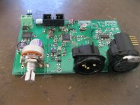
for the rest it operates as expected. enclosed a peek on the sigma studio diagram, and the analyzer signal showing a clean signal. signal generator was a minirator from neutrik instruments.
I also changed to pot to a nicer panasonic one.
Ok , I populated one board and found that I was tricked by eagle, as it's default npn sot-23 package has the emitter on pin 1, the left pin. so the mute transistors are now mounted belly-up. the only available reversed transistor I have found is the BFR92R the R meaning reversed.
for the rest it operates as expected. enclosed a peek on the sigma studio diagram, and the analyzer signal showing a clean signal. signal generator was a minirator from neutrik instruments.
I also changed to pot to a nicer panasonic one.
Attachments
open input S/N
now with the ADC input open, generator off.
currently the program has a gain of 2x , as I wanted to be able to clip the outputs.
there is a residual at 48kHz and for the purists, a 10uV rms residual at 49.6kHz coming from the "noisy" dcdc switcher. what a good layout and alu polymer capacitor can do.
Interesting to see the ADC input noise reducing down at the audio band edge. the ADC max input signal is 4V rms balanced (2V per leg) , while the output level is limited to 1.6V rms (0.8V per leg). still perfect for amps rated at +6dB (re 0.778V) full signal. the ADC is the usual limiting factor in the chain...
Attachments
Very fine results basreflex!
Please allow me some questions:
Is the board ready for production or does it need another revision?
Did you use Sigma Studio and/or dedicated software? Simga Studio seems freeware these days. (?)
It seems that this board only for a two way system? Am i correct on this?
Keep up this great project !
Please allow me some questions:
Is the board ready for production or does it need another revision?
Did you use Sigma Studio and/or dedicated software? Simga Studio seems freeware these days. (?)
It seems that this board only for a two way system? Am i correct on this?
Keep up this great project !
the board is 2 in 4 out. the input is wired as balanced XLR in (plus loop through) and the signals are subtracted in the digital domain. the outputs are wired as screw terminals and in the software currently configured as balanced by inverting one channel. but can be used as 4ch out if you give up the balanced features. also the unipolar signal is only half (0.8V rms max), somewhat under the usual sensitivity of power amps. the mono property makes it easy to run at 96khz fs and have enough MIPS to do all sorts of signal treatments. I hope the final cost will be low. only need to fix the sot23 error.
anyone that needs desperately the write back feature?
anyone that needs desperately the write back feature?
- Status
- This old topic is closed. If you want to reopen this topic, contact a moderator using the "Report Post" button.
- Home
- Source & Line
- Digital Line Level
- nanoDSP crossover, suggestions please