Hi everyone. I have been missing for a few weeks as everything that could happen... happened twice. So, I finally managed to get back home, and also back to tinkering and playing around with my vintage stuff (including the Citation 22 that I have not touched for the last month...). But I digress.
So,
I got a nice Nakamichi MB1 cd player, that had a bad laser, I replaced the KSS210 laser with a chinese part and that kept doing weird stuff (scratching noises in the playback, stopping altogether playing etc) although it read the TOC most of the times. . So I downloaded the service manual (of the MB2, since the MB1 manual is unobtanium), since I wanted to check eyepattern, rf and etc. maybe to adjust it.
And this is where I realize that the manual calls for an obscure object called the Nakamichi CD Test Set DA09155A, that features a few switches, BNC outputs for a scope and convenient connectors that latch on the MB.... I try to find some info on it (the MB2 manual only has a line art drawing of the thing) and find that is rarer than hen's teeth and that the one that surfaced a couple years ago went for like five times the value of the MB1 I have. Looking around, I find the manual for the Nak CD Player 2, which is basically the same thing as the MB2 in a different box, and inside, along the same drawing, there's a full schematic with part values and semiconductors of the set. First thing I realize, the thing is complex. Find the schematic below.
So I try to understand what it does, and it seems to have some oddball resistor value on many inputs, a full active filter that can select two slopes (I think), and a FET on the RF signal that I figure is amplifying the signal? Bottom line, I started designing a PCB for this and actually sourced all parts, including the op amps and the SK241 FET before asking myself: do I really need this? Is this something maybe other could be interested if it works? I know Nak used to build special a numbers of test sets for their decks to service them, that are expensive and difficult to find.
Point is, all the values and levels disclosed in the SM are relative of the signals as they come out of this box, and i have no idea how exactly the filters influence the original signal.
So here i am, can anyone hep me out? Opinions? even just to say, forget about it it's useless.
If instead it's ok, maybe this could be used to service all those Nak cd players out there, so why not, can you please help me out in making it a working set? I'd post full pcb files and BOM here.
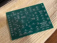
Note, there's an error in the PCB I'm posting now, as for connections to the FET. I just need to correctly move
 the GSD terminals


So,
I got a nice Nakamichi MB1 cd player, that had a bad laser, I replaced the KSS210 laser with a chinese part and that kept doing weird stuff (scratching noises in the playback, stopping altogether playing etc) although it read the TOC most of the times. . So I downloaded the service manual (of the MB2, since the MB1 manual is unobtanium), since I wanted to check eyepattern, rf and etc. maybe to adjust it.
And this is where I realize that the manual calls for an obscure object called the Nakamichi CD Test Set DA09155A, that features a few switches, BNC outputs for a scope and convenient connectors that latch on the MB.... I try to find some info on it (the MB2 manual only has a line art drawing of the thing) and find that is rarer than hen's teeth and that the one that surfaced a couple years ago went for like five times the value of the MB1 I have. Looking around, I find the manual for the Nak CD Player 2, which is basically the same thing as the MB2 in a different box, and inside, along the same drawing, there's a full schematic with part values and semiconductors of the set. First thing I realize, the thing is complex. Find the schematic below.
So I try to understand what it does, and it seems to have some oddball resistor value on many inputs, a full active filter that can select two slopes (I think), and a FET on the RF signal that I figure is amplifying the signal? Bottom line, I started designing a PCB for this and actually sourced all parts, including the op amps and the SK241 FET before asking myself: do I really need this? Is this something maybe other could be interested if it works? I know Nak used to build special a numbers of test sets for their decks to service them, that are expensive and difficult to find.
Point is, all the values and levels disclosed in the SM are relative of the signals as they come out of this box, and i have no idea how exactly the filters influence the original signal.
So here i am, can anyone hep me out? Opinions? even just to say, forget about it it's useless.
If instead it's ok, maybe this could be used to service all those Nak cd players out there, so why not, can you please help me out in making it a working set? I'd post full pcb files and BOM here.
Note, there's an error in the PCB I'm posting now, as for connections to the FET. I just need to correctly move
Maybe here?
https://www.manualslib.com/download/1332327/Nakamichi-Mb-1s.html
The MB-1 and MB1s are not the same,
as the 1s has a Sanyo laser. And the 1s uses a test unit DA09156A, but maybe it helps...
https://www.manualslib.com/download/1332327/Nakamichi-Mb-1s.html
The MB-1 and MB1s are not the same,
as the 1s has a Sanyo laser. And the 1s uses a test unit DA09156A, but maybe it helps...
Awful. Same with the first CD-Naks fon the market, OMS-5 and 7.
Optically the looked identical.
Mark one was C.E.C and Philips based (The Kyocera-DA910 is the same)
Mark 2, the OMS-5II/7II were Sony based, with D/A coversion from Burr-Brown,
Oversampling filter from NPC.
Back to MB1.
As far as I remember, in general aligning E-F Balance should be relatively easy as
it peaks symmetrical around 0V when aligned.
Best observeable when jumping from track to track or pressing Forward and Rewind.
Yeah I know, the -s versions are really several steps back in terms of quality and performance.... in any case, I ordered a pcb set from jlcpcb and once I receive it I’ll try it out. There are many readings that make little sense, and it’s the reason why I am trying to replicate the Nak CDTest set.
here’s the MB1 I’m trying to fix

here’s the MB1 I’m trying to fix
So after some consideration, I found out that the Nakamichi CD Test Set DA09155A is just the name of the "black box"; it's the kit itself that changes name when it is coupled with the specific cables for different models - but the circuit box is always the same. As a matter of fact, the PCB I am presenting here will should work for all of these CD Player models from Nakamichi:
CD Player 1,2,3,4
MB-1,2,3,4
MB-1s,2s,3s,4s
Sound Space 7
1000Mb/i, 1000Mb
CD Cassette Player 1
at least IF I have done the job well.
CD Player 1,2,3,4
MB-1,2,3,4
MB-1s,2s,3s,4s
Sound Space 7
1000Mb/i, 1000Mb
CD Cassette Player 1
at least IF I have done the job well.
Hello Pizzigri,
It is very interesting what you are doing. I would be interested to buy the PCB for the reason of convenience. Now, I have to make separate connections with my scope with the risk of damaging something. So please let me know if you are going to sell the PCB. I was able to repair almost every Nakamichi CD 1, 2 and 3. My experience shows that in any case you have to exchange all the capacitors on the RF AMP PCB next to the laser. In a few cases I had to exchange the laser. @chapai123 you can test the CD transport by shortening the RAM RESET connectors.
It is very interesting what you are doing. I would be interested to buy the PCB for the reason of convenience. Now, I have to make separate connections with my scope with the risk of damaging something. So please let me know if you are going to sell the PCB. I was able to repair almost every Nakamichi CD 1, 2 and 3. My experience shows that in any case you have to exchange all the capacitors on the RF AMP PCB next to the laser. In a few cases I had to exchange the laser. @chapai123 you can test the CD transport by shortening the RAM RESET connectors.
Hello pizzigri,
I'm new to this forum and signed up because I find your project very interesting. I am currently busy repairing a Nakamichi CD Player 2. I've already replaced the belts, but only CDRs sound well, but not the purchased ones, these sound like scratched Vinyl. Next thing is to replace the capacitors, as Wolf F. suggests. Wolf, Do all capacitors need to be replaced or just the electrolyte? I would then like to carry out the adjustment work with a DA09155A.
I already have the electronic parts for it and previously wanted to build a freely wired circuit board, but your concept is much more precise.
So can you sell me one of your PCBs? I need shipping to Germany if possible.
- Home
- Source & Line
- Digital Source
- Nakamichi CD Test Set DA09155A