Hi Everyone.
After reading about Naim's product, I'm interested in producing a replica but not sure of which design to base my project on.
There's the design of the NAP135 from Neil McBride
www.neilmcbride.co.uk/jknamps.html
and the original schematic of the NAP250 from previous "MEGA" Naim forum.
Neil says the only difference between 250/135 is the PSU. But looking at the original and Neil's one, his is missing a pair of transistor and other associate component. Is this intentionally
and for what reason?.
Naim says that there is no difference in the two in term of quality, only different in power handling (NAP135 has 75W to 70W of 250). Big diffs hey...5Watts!!!, yet the 250 is more expensive...why?. Which one is best model in quality.
I really want to get start on building the thing, but so confuse as to which one to build.


Thanxs in ADV
Minh
After reading about Naim's product, I'm interested in producing a replica but not sure of which design to base my project on.
There's the design of the NAP135 from Neil McBride
www.neilmcbride.co.uk/jknamps.html
and the original schematic of the NAP250 from previous "MEGA" Naim forum.
Neil says the only difference between 250/135 is the PSU. But looking at the original and Neil's one, his is missing a pair of transistor and other associate component. Is this intentionally
and for what reason?.
Naim says that there is no difference in the two in term of quality, only different in power handling (NAP135 has 75W to 70W of 250). Big diffs hey...5Watts!!!, yet the 250 is more expensive...why?. Which one is best model in quality.
I really want to get start on building the thing, but so confuse as to which one to build.
Thanxs in ADV
Minh
NAP250 NAP135
HI Minh,
The Price of the NAP135s is virtually double the price of the NAP250 this is because the NAP135 is a Monoblock, essentially its a NAP250 with one amplifier channel taken out and a fan added. The actual amplifier circuit is the same, I have owned both so this is truth not opinion.
The Circuit on Neils site has no protection Circuitry (apart from the current limiting on the Regulator Board), that is what those extra transistors are on the original.
As to the sound I do know people who prefer the NAP250 and others who prefer the NAP135s
Mozfet
Minh,
All the old (not NAP500) style Naim amps are basically the same circuit. The 250 and 135 have psu regulators. If it were me I'd build the amp circuit first and get that working ok and then add a psu regulator.
Bear in mind that Neil McBride does not understand how the Naim amp circuit works. In other words, following his instructions will get you a working amp but it will not be of "audiophile" sound quality (this high feedback design needs a lot of attention to output devices for it to sound great). In other words it will be a fun build experience and will probably sound pretty good but don't expect it to rival a real Naim - it certainly won't.
BAM
250/135 Clones
It's a relatively simple task to build a 250/135 clone from either the details on Neil McBrides site or from my site:
www.users.zetnet.co.uk/avondale
The Naim amps have a couple of generic problems which I've managed to solve simply by the addition of an output inductor and a couple of emitter resistors in the input long tailed pair. The Naim circuit's so called protection circuitry has also been removed as it operates at very much lower levels than at first thought and produces the characteristic Naim 'glare' over the music. Measurements and listening tests indicate it is perfectly possible to improve significantly on the original manufacturers performance.
Cheers,
LesW
Keep it real
Les,
Judging by your published "NAP Series Amplifiers - Revised Circuit" you also don't know how the Naim circuit works.
"it is perfectly possible to improve significantly on the original manufacturers performance"
Oh please. I think this is a good, honest site that Nelson's set up and is not an appropriate place to make exaggerated marketing claims for your services, especially ones that you cannot back up. Keep it honest here at least.
BAM
Naim Circuit
Judging by your published "NAP Series Amplifiers - Revised Circuit" you also don't know how the Naim circuit works
In that case Bam, perhaps you'd be kind enough to share with this small but select group your understanding of how the Naim circuit works.
I tender my gratitude in advance,
LesW
Judging by your published "NAP Series Amplifiers - Revised Circuit" you also don't know how the Naim circuit works
In that case Bam, perhaps you'd be kind enough to share with this small but select group your understanding of how the Naim circuit works.
I tender my gratitude in advance,
LesW
hi lesw ,
have two rather novel totally high end amp. designs you may want to have for small fee
indeed they could form part of an entirely new range for your firm...
see also my paper on VI protection in october issue of electronics world at your local WH Smith....
mikek in chigwell essex...
,have two rather novel totally high end amp. designs you may want to have for small fee
indeed they could form part of an entirely new range for your firm...
see also my paper on VI protection in october issue of electronics world at your local WH Smith....
mikek in chigwell essex...
Firstly, shouldn't the removal of the protective circuitry improve sound quality?, on the basis of a purer circuit.
Secondly, what would be the recommending output device, since Naim had theirs' custome made?.
Thirdly, does anyone have PCB layout for this amp?
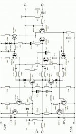
Finally, can someone verifies that the schematic I've got is the original design?.
I'll now build the amp module first, if that works ok and if budget permitts, I'll build the monoblock.
Secondly, what would be the recommending output device, since Naim had theirs' custome made?.
Thirdly, does anyone have PCB layout for this amp?
Finally, can someone verifies that the schematic I've got is the original design?.
I'll now build the amp module first, if that works ok and if budget permitts, I'll build the monoblock.
Attachments
hi minh
No...the removal of the protection circuit should'nt neccesarily improve real or perceived performance unless the protection circuit is incompentently designed in the first place.
Looking at the circuit you've posted, there are quite a few things intrinsically wrong with it...the first being of course, the absence of SOA protection, and DC-offset protection.
In addition, the base resistor of the high-side drive transistor should be directly connected to the collector of the bias-generator transistor, and not to the top of its collector resistor...
Thirdly, the collector resistor in the input diff. pair are appalingly mismatched, presumably to deliberately increase the generation of even-order harmonics...i would definetly delete the 22K resistor, as it serves no usefull purpose whatever
Further, the diff. pair is undegenarated...its DC bias resistors, (ie feedback and input Thevenin resistances), are mismatched...giving rise to needless DC offset...
Oh...and the 330pF, (+4K7), at the input is much too high a value for simple RF filtering...needless roll-off with less than heroic pre-amps and interconnects....
In addition the 68uF cap in feedback arm is much too small...makes for generous production of LF capacitor distortion...use of back to back 470uF electrolytics to create non-polarised cap. much better, as there is insufficient polarising voltage for electrolytic in this position....etc
In general, i would steer well clear of the thing...
Hi Minh
You may by now have gathered that i am not exactly a fun of Naim type designs, or indeed the originals.....Indeed, i think you'll find that the original does not differ significantly from this incarnation, with the possible exception of course, of a rather rudimentary single-slope linear-foldback SOA protection scheme...
I would recommend a thorough reading of a paper by yours truly in the september issue of electronics world.....i will, in addition, be publishing a rather new approach to ultra-high end amplifier design in the same journal in the near future....watch this space.....
Nearly the origional. The ZTX753/653 were not available at that time. Protection circuit used different values for each half. Back emf diode protection were not 1N4005 and I don't remember if the DC blocking capacitor was 68U. If you use different output transistors you will need to modify the phase compensation networks to match.
Re: hi minh
this would make the usable voltage swing smaller, as all the current reaching the high side driver would go through that resistor.
removal could influence the stability - think of the miller capacitance at (-)input of the differential pair.
degeneration: I have a paper in French where degenerated input stages where measured in terms of distortion -> no difference to undegenerated. OK, noise will go up and the slew rate, too.
+input has 4k7 plus 22k bias current resistance
-input has 27k bias current resistance
what a big difference ,-)
330pF and 4k7 yield -3dB at app. 90khz (I am doing the maths in head, no calculator used, and I might be off a bit)
- so you would like to have an AM radio amp rather
68uF and 1k yield -3dB at app. 2Hz - is this a problem ?
please please show us how to make it better
regards,
Hartmut from Munich
mikek said:
[...] the base resistor of the high-side drive transistor should be directly connected to the collector of the bias-generator transistor, and not to the top of its collector resistor...
this would make the usable voltage swing smaller, as all the current reaching the high side driver would go through that resistor.
Thirdly, the collector resistor in the input diff. pair are appalingly mismatched, presumably to deliberately increase the generation of even-order harmonics...i would definetly delete the 22K resistor, as it serves no usefull purpose whatever
removal could influence the stability - think of the miller capacitance at (-)input of the differential pair.
Further, the diff. pair is undegenarated...its DC bias resistors, (ie feedback and input Thevenin resistances), are mismatched...giving rise to needless DC offset...
degeneration: I have a paper in French where degenerated input stages where measured in terms of distortion -> no difference to undegenerated. OK, noise will go up and the slew rate, too.
+input has 4k7 plus 22k bias current resistance
-input has 27k bias current resistance
what a big difference ,-)
Oh...and the 330pF, (+4K7), at the input is much too high a value for simple RF filtering...needless roll-off with less than heroic pre-amps and interconnects....
330pF and 4k7 yield -3dB at app. 90khz (I am doing the maths in head, no calculator used, and I might be off a bit)
- so you would like to have an AM radio amp rather
In addition the 68uF cap in feedback arm is much too small...makes for generous production of LF capacitor distortion...use of back to back 470uF electrolytics to create non-polarised cap. much better, as there is insufficient polarising voltage for electrolytic in this position....etc
68uF and 1k yield -3dB at app. 2Hz - is this a problem ?
In general, i would steer well clear of the thing...
please please show us how to make it better
regards,
Hartmut from Munich
hi hartmut
1] Removal of the 22K resistor will not affect stability...all it does is contribute to needlees quiescent current mismatch in the diff. stage, a recipe for the generous production of needless even order harmonics...
2] The resistor in the collector of the bias generator is supposed to compensate for bias voltage drift with current.....connecting the high side driver to the top of this resistor only aggravates the tendency for bias to increase with non-ideal increase in current...
3] The degeneration of the input pair constitutes local negative feedback...any elementary text should tell you that...this leads directly to the reduction in transadmittance of the diff. pair, (conducive for easy stabilization without an inordinately large miller capacitor across the transimpedance stage). It also leads to an improvement in the linearity of the pair, (see grey and meyer, or indeed Self...third edition) ...that French paper is plain wrong...pardon my french..
4] Mismatched feedback and input bias resistors is unnecessary, inelegant, and reeks of a lack of commitment and attention to detail...
5] Use two-pole compensation around transimpedance stage instead of single pole miller stabilization...this maximises the global feedback factor at higher audio frequencies..
6] For the rest of your concerns i would refer you to randy slones and douglas self's books....
cheers!
mikek said:1] Removal of the 22K resistor will not affect stability...all it does is contribute to needlees quiescent current mismatch in the diff. stage, a recipe for the generous production of needless even order harmonics...
well, at 1mAmp collector current the voltage amplification in 22k resistor is about 500, and the miller cap is 500 times 3pF (assuming this is the reverse capacitance) equals 1500pF. Having these 1500pF or not (in the case you remove the resistor) will affect the high frequency behaviour and might affect stability. Now you say that doesn't matter, and try to teach things.
3] The degeneration of the input pair constitutes local negative feedback...any elementary text should tell you that...this leads directly to the reduction in transadmittance of the diff. pair, (conducive for easy stabilization without an inordinately large miller capacitor across the transimpedance stage). It also leads to an improvement in the linearity of the pair, (see grey and meyer, or indeed Self...third edition) ...that French paper is plain wrong...pardon my french..
Mr Perrot measured distortion by output voltage, which is the only right way. If you measure distortion by input voltage, of course you get lower distortion through the degeneration. Noise is added, too. Just calculate the equavalent noise resistor, you can surely find that in one of your books.
I will not try to talk degeneration down, but the input stage is the last stage I would put degeneration.
IMO, degeneration in inputs is only useful to make the max differential voltage higher, and to control slew rate for hi-speed FM frequency application. If degeneration is necessary to make an amp stable, then compensation methods are chosen inadequate. For further reading, I recommend Dostal: Operational Amplifiers, the chapter on Compensation Methods.
4] Mismatched feedback and input bias resistors is unnecessary, inelegant, and reeks of a lack of commitment and attention to detail...
please look: 4k7 plus 22k for the (+)input bias is 26k7, which is 1% difference from 27k for the (-)input bias, so where is the mismatch ? I recommend reading a math book at this point, but not a too complicated one
regards,
Hartmut
This thread is getting really interesting.
I'm right behind hifidaddy's reasoning and AV's comments.
Mozfet wrote: "I'd really like to know how the NAP250/135 circuit operates, you are going to tell us all aren't you?"
No.
It was a long and gruelling road for me to figure this stuff out. I'll help but I'm not just going to give it all away. Also, probably not fair to Naim. In this forum I'm trying to share ideas and approaches; hopefully helping people to think about things in the right way and correct theory mistakes when they arise, and to soak up some of the snake oil that gets spilt ocassionally.
- Status
- This old topic is closed. If you want to reopen this topic, contact a moderator using the "Report Post" button.
- Home
- Amplifiers
- Solid State
- Naim NAP135 vs NAP250...which one?