Output transistors would be the first to check, but there may be more bad parts (particularly drivers and the feedback-side transistor in the input pair, but dead Rs, Ds and Cs are not unusual either). The mean thing about DC-coupled power amps of a certain complexity is that they tend to blow up again in no time if you overlook the tiny little thing that cause the fault in the first place. Bulb tester highly recommended.
Reportedly the basic circuitry for the NAP 110, 140 and 250 is essentially the same, so a schematic for any of these should do. Pretty standard circuit AFAICS, except for a quasicomp output stage.
Reportedly the basic circuitry for the NAP 110, 140 and 250 is essentially the same, so a schematic for any of these should do. Pretty standard circuit AFAICS, except for a quasicomp output stage.
Last edited:
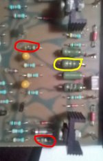
Three dead resistors (two burnt, one shorted).
Transistors seem ok. Would you someone suggest me a proper replacement for the power resistors please? I think I should replace all of them and in both boards.
Transistors seem ok. Would you someone suggest me a proper replacement for the power resistors please? I think I should replace all of them and in both boards.
Attachments
Last edited:
These are probably close to the original type, which are 3W in all the old Naim amplifiers. http://www.welwyn-tt.com/pdf/datasheet/WA80.PDF
It doesn't really matter what brand WW as long as it fits the PCB but its a good idea to mount any power resistor a few mm clear of the PCB to avoid fire when accidents like that one occur. You could use 2W metal film even but Metal oxide or flameproof types would be safer. I'm puzzled about the shorted resistor, though. Only a few turns could short and reduce its value by a few percent maybe. Are you certain it is the resistor itself that is shorted?
It doesn't really matter what brand WW as long as it fits the PCB but its a good idea to mount any power resistor a few mm clear of the PCB to avoid fire when accidents like that one occur. You could use 2W metal film even but Metal oxide or flameproof types would be safer. I'm puzzled about the shorted resistor, though. Only a few turns could short and reduce its value by a few percent maybe. Are you certain it is the resistor itself that is shorted?
Last edited:
2 possibilities:
Is your meter accurate at low resistance values, have good batteries and does it read zero R when probes are shorted?
Do all the 8 WW resistors read the same value? There are actually 4 WW resistors in each channel when the standard
circuit shows just 3 resistors. That's one resistor from each output transistor (emitter on the positive rail side,
collector on the negative rail side) to the output common rail and 2 in parallel from that point to the speaker terminal.
However, NAP 110 is an early model (1979-87)and may have some minor differences. I would not expect the output
resistor to be larger than 0R22 though. Look at the PCB tracks beneath or use some backlight to see what the actual
circuit is.
BTW, There is only one schematic for all early NAP models so you won't find one specifically drawn up for any model,
apart from wiring diagrams for the bridged models - unless another DIY or service technician drew them up.
Last edited:
Ian, you're right: my DMM isn't that accurate. It reads R3 when probes are shorted: the resistors are marked R22 and so they are. Yes there are 3 of these R22 resistors, the fourth one is 8R2 that go to ground in series with a 220nf capacitor as in schematic. And checked again, no shorted resistors they are just burnt (do I need a new meter?). Transistors, diodes, etc under the probes behave like the ones in the other channel, so first I'm going to replace just the faulty resistors.
Last edited:
That's good but I think you need a better meter - they are so cheap now, and you can check specifications before buying. Usually, you won't need to replace WW resistors immediately, even if the coating has burned. When you have replaced the small, burned MF resistors, you could try it like that, as the small WW resistors may be hard to obtain.
As always, use a bulb limiter when you power up a repaired amplifier.
I actually use a 100R/OW5 resistor in each power rail lead of my own DIY amplifiers and this also works well, with the benefit that 100R is convenient for measuring voltage drop and calculating current. This is very good for spotting trouble before it destroys your work.
Simply remove power rail fuses (if fitted) and solder the resistors across the fuseholder or use any method to insert them securely in the supply wiring during testing. As Naim use square pin connectors for the power, it should be easy to fit resistors temporarily by wrapping one lead around the pin and folding the other to insert in the connector.
That's good but I think you need a better meter - they are so cheap now, and you can check specifications before buying.
May you suggest a decent one?
By the added artwork to the standard Naim circuit, I guess that was one of Les Wolstenholme's (Avondale Audio) Naim mod circuits and is close to his NCC200 design. (see below). The original is said to follow the early NAP250 (1975) design but any variations across many models up to the late 1980s were minor. The differences to the NCC200 (still offered for sale) are removing the VI limiter circuit, adding "anti-rail sticking" diode/resistors, output coil and damping resitor, substituted transistors and I imagine, his own degree of parts matching.This circuit may be of help. I found it on the web some time back, therefore I don't know how accurate it is.

Hi Calamaro,
I hesitate to recommend a DMM for you as your local suppliers may have different brands even though they may be the same as mine and come from the same Chinese factory! Fluke now have budget meters that are basic but reliable Chinese products and you can buy them from many suppliers. I think Fluke 15 is a good basic meter.
Multimeter UNI-T UT71E
Here is a cheaper model and still quite good - check the variations like A,B,D,E for features and different accuracy too. Take a close look at resistance accuracy and range of measurement possible - this can be a problem for low cost instruments, as you found. Multimeter UNI-T UT61B.
Buying direct from China can be cheaper than these examples too - shop around, read reviews by professional people, even buy a used one if the meter is a really good model too.
")
Last edited:
When you have replaced the small, burned MF resistors, you could try it like that, as the small WW resistors may be hard to obtain.
Replaced the two burned resistors but one of them burned again when I've switched on
You haven't identified what these resistors are but guessing from the fuzzy PCB traces showing in your pic, the burned resistors were 100R from each OR22 resistor (not the output resistor) to the bases of TR7,8. i.e. the current sense voltage for the VI limiter circuits. If these are the burnt resistors (please check) it would be unusual if TR7,8 were not also shorted or the 47R resistors or capacitors also damaged. Test Vbe on TR7,8 and also test quiescent current by measuring voltage across either OR22 resistor. You should measure around 6mV or, if the reading is not clear, 12mV across the 2 in series. The output offset voltage (from the output to speaker ground) should be less than 40 mV.
Otherwise, the other 100R resistors from the same point are the driver emitter resistors and that points to problems with the MJE243/253 drivers (on small heatsinks). Test them for shorted C-E and Vbe. ) Voltage between base and emitter is always approx. +/- 0.65V for all bipolar transitors. Always compare voltages with the good channel so others understand what is likely wrong and you gain some clues for troubleshooting.
Note: The part numbers refer to Naim's schematic, similar to the last schematic posted above.
Last edited:
Bad news
Checked again with my unpredictable DMM (a Fluke one btw) - while the two replaced resistors were in the flames - and:
-one output transistor is shorted
-its driver transistor (MJE243) has open C-E, Vbe is 11,58 volts
-the other driver transistor (MJE543) has open C-E, Vbe is 0,65v
-1n004 diodes between + and - rail are open
-DC offset from faulty channel: 29 volts
-maybe you remember that one ww 0R22 resistor was also burnt
and I noticed that plastic connectors from pcb to red speaker terminals are a bit melted
also I wonder why my bulb tester isn't glowing
Well, it seems you have trouble everywhere. I guess these faults in the amplifier were there all the time and that's why it was for sale (hopefully very cheap in that condition).
OK, I think from your description that just one side, TR9, TR11(MJE243) are blown. That would make sense and of course, the output offset voltage would have told you that if it was so high. Perhaps you misunderstood what was meant in post #4 or your meter has an intermittent fault/ flat battery.
I think all those parts TR9,10,11,12 should be replaced but this channel will then not match the other. MJE243/253 are not difficult to obtain and you only need 1 each.
The output transistors, TR11,12 may be marked BDY58 as the schematic shows or they could have been replaced earlier with Naim "house code" parts NA001 - neither will be easily or cheaply available. The best substitutes for quality sound will be MJ15003 but BUV20 is now also rated highly. Modifying Naim Audio power amplifiers
You already know what to do about burnt resistors - the smaller types are 500 or 600 mW MF resistors and the diodes are not critical- any 1A rated general purpose rectifier diode with a voltage rating of 200V or greater will be fine, so IN4004 is fine too. Before repairing the damaged channel, you should test the VAS transistors, ZTX653,753. these will cause the output stage to blow if they are damaged too, so take care to measure all transistors, noting that in some places it is not simple to test with certainty unless you remove them. I have found the cheap and basic Ebay transistor testers to work well for checking out small transitors and drivers. They actually identify, show connections and test almost any component you can find - this is just the cheapest example I saw @ ~14 Euros. There are many other versions with better features, connectors etc: LED Backlight Transistor Tester Capacitor ESR Inductance Resistor NPN PNP Mosfet | eBay
I suggest you repair the damaged channel first, listen and think about the sound quality and then consider changing the output transistors in the other channel.
First, open up the meter and check there are no loose sockets, connectors etc. It seems like there could be a poor connection somewhere but be careful not to move any adjustable pots. which set factory calibrations.
Last edited:
Ian, your help is very precious: thank you.
Well I'm going to order the parts I need, probably I'll try a couple of MJ15003 as they are cheap but if the amp will be repaired I would like to use original power transistors, aren't BDY56 in the old NAP 110? Found this picture on the web. They also seem a lot cheaper than BUV20. There are a few sellers on that auction site but I feel a bit anxious about fakes: do someone knows a reliable supplier?
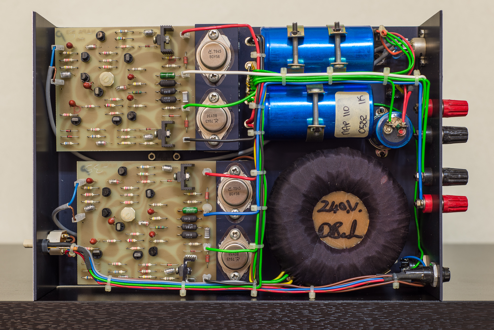
Well I'm going to order the parts I need, probably I'll try a couple of MJ15003 as they are cheap but if the amp will be repaired I would like to use original power transistors, aren't BDY56 in the old NAP 110? Found this picture on the web. They also seem a lot cheaper than BUV20. There are a few sellers on that auction site but I feel a bit anxious about fakes: do someone knows a reliable supplier?
- Status
- This old topic is closed. If you want to reopen this topic, contact a moderator using the "Report Post" button.
- Home
- Amplifiers
- Solid State
- NAIM NAP 110 amp, high DC offset and mute channel