Hi,
Just bought cheaply 3 year old NAD C350BEE for repair. It has problem witth the output volume. Even when volume is set to max, you can barely hear the sound. I only tested it with headphones and i noticed that only the left channel is working. When switching between audio sources the sound cracks loudly.
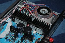
I started by making a visual check. It seems that 4 biggest capacitors has leaked, or NAD uses some type of glue undernearth capacitors? Tested all capacitors with meter but did not found any shortings.
Power LED is staying at RED so i think it has some protection circuit on?
Can someone give a hint what kind of errors can cause such symptons? I have been playing a little with electronics but never done anything with the amplifiers.
Thanks in advance
Samu
Just bought cheaply 3 year old NAD C350BEE for repair. It has problem witth the output volume. Even when volume is set to max, you can barely hear the sound. I only tested it with headphones and i noticed that only the left channel is working. When switching between audio sources the sound cracks loudly.
I started by making a visual check. It seems that 4 biggest capacitors has leaked, or NAD uses some type of glue undernearth capacitors? Tested all capacitors with meter but did not found any shortings.
Power LED is staying at RED so i think it has some protection circuit on?
Can someone give a hint what kind of errors can cause such symptons? I have been playing a little with electronics but never done anything with the amplifiers.
Thanks in advance
Samu
What you see under the capacitors is most likley glue. however i have seen many of these amplifiers and all needed a re cap. Replacing the caps will maybe fix your protection mode problem. Before changing the caps i would have a test around the output stage and check for shorted transistors .
Last edited:
Yes glue. A bit acidic too. Clean it up.
Noise on switching is usually dirty contacts. Is this mechanical switches, relays or solid state? I hope you have the schematic. Poking around blind is pretty tough. Compare the DC numbers all around the two sides.That may give you a hint. Of course, with a feedback amp, if one is off, everything is off. Amps can be a real pain that way.
Noise on switching is usually dirty contacts. Is this mechanical switches, relays or solid state? I hope you have the schematic. Poking around blind is pretty tough. Compare the DC numbers all around the two sides.That may give you a hint. Of course, with a feedback amp, if one is off, everything is off. Amps can be a real pain that way.
This model uses a remote controled motor operated volume pot. it also uses a mix of solid state and mechanical switching . They also tend to run on the warm side and this is a big factor in the capacitors drying out . Also it uses nads power envelope psu . Theses amps sound very well when they have had some tlc and a capacitor change
Thanks for quick answers. I have the schematic and full service manual.
I checked the voltages from power circuit to the main circuit. It seems that power circuit does not work as it should (or protection mode cuts it)
I measured te voltages from cable (5 leads) which comes from power circuit to main circuit and there was only one voltage supply, 3.3VDC. There should be 45V, 17V and 5V coming from power cirvuit so i think i need to look that problem closer.
Ill be testing more tomorrow and let you know the progress.
Because the electrolytic caps are partly close allocated to the heatsinks they are exposed to high thermal stress.
This devices I would replace in any case.
Who was here the developer for such a PCB design?
Actually I cannot believe, that this was Mr. Björn Eric Edvardson, the developer from the circuit topology.
But the kind of heatsink mounting from the power output devices is a good approach.
This devices I would replace in any case.
Who was here the developer for such a PCB design?
Actually I cannot believe, that this was Mr. Björn Eric Edvardson, the developer from the circuit topology.
But the kind of heatsink mounting from the power output devices is a good approach.
Attachments
Last edited:
Maybe Bjorn did the layout, maybe he just did the circuit. Unless he is watching, we may never know. NAD takes quite a beating, and their older reliability history makes it somewhat justified, but they still provide decent performance for the price. In their price range, there is a lot of real trash. They at least try.
Do you have a variac? Makes this kind of work not quite as dramatic. (Kill the protection and bring it up slowly)
Expected life for an electro is 8 years IF they are not abused, like getting warm. 3 to 5, yeas? I can believe that!
I might be inclined to cut open the case bottom and top replacing the louvers with more open screen, and put slightly taller feet on it. After you get it working of course.
I do not have variac :/. Voltages from power circuit to main circuit seems to be ok when i did the measurements again.
Today i measured power supply 10000uF 50V capacitors with a meter. Or i quess i did it right: using a ohmeter i measured that the Ohm value of other one of those kept rising a lot faster and higher than other (red wire to positive side). I compared the results to new caps almost same value.
Also measured voltages on caps when power is on.. 47,2V is ok? (manual says it should be 45V). Also other cap lost its voltage very quickly compared to another one when power was shut off.
Ordered two new Panasonic TS-HA caps from ebay. Also bought two smaller Elna caps so i can replace all the capacitors which has weird "glue" underneath.
Quickly took out TLC resistor, seems it gives around 47ohm all the time. 45ohm on top of it.
Meant 45 ohm when ice is is on top of it. No luck either with diffrent resistors 100 - 330 ohm in TLC thermistor place.
Currentrly running out of ideas..
Below is a part of protection schematic. I am confused how the left part of schematic is working. How the protection module gets information about the temperature (resistance from R330 thermistor) to know when to cut the power circuit? Protection module is UPC1237. Also i thought that that standby signal is input signal at this part of schematic, but the diode D311 puts and end for that thought (voltage cannot be high enought to get pass it to continue to R339).
I uploaded the full schematic to here: http://levyhylly.entrada.fi/schematic.pdf
Thanks in advance.

I uploaded the full schematic to here: http://levyhylly.entrada.fi/schematic.pdf
Thanks in advance.
Last edited:
Since pin 8 of the protection module is Vcc (which should be 25..60 V), the only thing I can think of is that the left part cuts power to the protection module in certain situations (which automatically leads to speakers being disconnected as the speaker relays aren't driven anymore by the module).
Q315 works more or less as a switch here and if it conducts, it will pull Vcc on pin 8 down to ground. R342 limits the current to a safe level.
This happens either when the standby signal is active or the temp rises high enough. D310 and D311 are there to prevent the standby part and the temp part influencing eachother.
Without Vcc on pin 8, the protection module obviously won't operate, which automatically means the speaker relays open.
It adds overtemp protection and stanby disconnection of the speakers to the protection module's offset and overload protection.
Last edited:
Since pin 8 of the protection module is Vcc (which should be 25..60 V), the only thing I can think of is that the left part cuts power to the protection module in certain situations (which automatically leads to speakers being disconnected as the speaker relays aren't driven anymore by the module).
Q315 works more or less as a switch here and if it conducts, it will pull Vcc on pin 8 down to ground. R342 limits the current to a safe level.
This happens either when the standby signal is active or the temp rises high enough. D310 and D311 are there to prevent the standby part and the temp part influencing eachother.
Without Vcc on pin 8, the protection module obviously won't operate, which automatically means the speaker relays open.
It adds overtemp protection and stanby disconnection of the speakers to the protection module's offset and overload protection.
Ok thanks for clarification. This is weird: just measured voltage at the R342 and it seems that other end has 47,2V and other end 5V so it is just 5V at the protection module VCC pin 8 (also took a measure from there).
I connected pin 6 on protection module (relay pin) to earth and got the amplifier working, somehow at least: still testing with headphones and only left side working but now loud and clear. Also the light turned to blue. It seems that there really are something wrong with the right speaker line couse it isnt working and that prevents protection circuit to engage relay.
Ok thanks for clarification. This is weird: just measured voltage at the R342 and it seems that other end has 47,2V and other end 5V so it is just 5V at the protection module VCC pin 8 (also took a measure from there).
Took Q315 off from the board in hope that protection would be off. Still red light and 5V at the pin 8.. Should i take protection module off and then measure voltage again?
After having another look at the datasheet of the uPC1237, I noticed that even though they specify Vcc at 25..60 V, the maximum voltage at pin 8 should be 8 V or less.
In other words: measuring 5 V at pin 8 is not wrong. It's also no wonder that removing Q315 didn't change a thing, but at least now you know that the overheat and standby protection aren't the cause.
I connected pin 6 on protection module (relay pin) to earth and got the amplifier working, somehow at least: still testing with headphones and only left side working but now loud and clear. Also the light turned to blue. It seems that there really are something wrong with the right speaker line couse it isnt working and that prevents protection circuit to engage relay.
Connecting pin 6 to ground will close the circle and operate the speaker relay. But the speaker relay should not affect the headphones output. The signal for the headphones is taken directly from the power amps outputs before it enters the speaker relay. Whether the speaker relay is switched on or off should therefore not matter.
However, plugging in the headphones does cut power to the speaker relay. If you look at the phones socket JK31 in the lower right corner of the schematic you'll see that it is equipped with a contact that cuts the 35 V going to the relay when a plug is inserted. So any tests to see if the relay clicks must be done without headphones connected.
It is worth disconnecting the headphone board and temporarily shorting pins 1 and 2 of connector CB31 together. This rules out any problems with the headphones socket (you might be surprised at what small children try to put into those).
If you look at page 2 of the datasheet I linked to, you'll see a table of threshold voltages for the detection inputs. Next step would be to measure them and see if any are on the "wrong" side of the threshold. If so, this means there's a fault that you then need to trace. Please post measurements of those voltages so that we can have a look.
Good luck!
After having another look at the datasheet of the uPC1237, I noticed that even though they specify Vcc at 25..60 V, the maximum voltage at pin 8 should be 8 V or less.
In other words: measuring 5 V at pin 8 is not wrong. It's also no wonder that removing Q315 didn't change a thing, but at least now you know that the overheat and standby protection aren't the cause.
Connecting pin 6 to ground will close the circle and operate the speaker relay. But the speaker relay should not affect the headphones output. The signal for the headphones is taken directly from the power amps outputs before it enters the speaker relay. Whether the speaker relay is switched on or off should therefore not matter.
However, plugging in the headphones does cut power to the speaker relay. If you look at the phones socket JK31 in the lower right corner of the schematic you'll see that it is equipped with a contact that cuts the 35 V going to the relay when a plug is inserted. So any tests to see if the relay clicks must be done without headphones connected.
It is worth disconnecting the headphone board and temporarily shorting pins 1 and 2 of connector CB31 together. This rules out any problems with the headphones socket (you might be surprised at what small children try to put into those).
If you look at page 2 of the datasheet I linked to, you'll see a table of threshold voltages for the detection inputs. Next step would be to measure them and see if any are on the "wrong" side of the threshold. If so, this means there's a fault that you then need to trace. Please post measurements of those voltages so that we can have a look.
Good luck!
Thanks for helping! Its nice to see that there really are some people that are helping also rookies
")
Late yesterday night took measurements from all pins and got this: (multimeter ground connected to speaker ground)
pin 1 0,002 V
pin 2 0 V
pin 3 0,002 V
pin 4 -17,75 V
pin 5 0 V
pin 6 31,70 V
pin 7 0,55 V
pin 8 4,97 V
Pin 5 seems to be ground so thats ok.
Pin 6 voltage comes from other side of circuit and needs to be grounded by module to run the relay.
Pin 7 comes from mute, i think that is ok.
Pin 8 is VCC and seems to be ok.
The rests seems to be weird, atleast pin 4. Does the text "level to invert at pin 6" that it switch pin 6 to ground at that voltage or cuts it off? I mean if it cuts, then all the the pins 1, 2, 4 needs to be at the threshold to run speaker relay.
Ill try shorting the headphone pins later today
Ill try shorting the headphone pins later today
Shorted CB31 pin 1 and 2. No difference, still in protection mode.
Made a cable for easy shorting pin 6 to ground, so that i could measure both speaker channels voltages. It shows that both channels are working fine (0 - ~35VAC). Without short cable i could not locate any voltages at R176 and R276 (=signal voltage).
Can it be that UPC1237 is broken?
Can it be that UPC1237 is broken?
- Status
- This old topic is closed. If you want to reopen this topic, contact a moderator using the "Report Post" button.
- Home
- Amplifiers
- Solid State
- NAD C315BEE - Help with repair!