I am writing this forum in regards to a NAD 7250PE that I'm working on.
I'm familiar with amp repair, but not enough that I can fully understand a schematic to know which potentiometer to adjust for DC offset and Idle Current.
I spoke with Mooly who is quite knowledgeable, and received this response in regards to adjustment:
"Idle current adjustment is via preset R624 and checked via the voltage between test points TP601 and TP602 located on the emitter resistors of the output transistors. I would guess a safe value would be around 9 millivolts DC giving around 20 milliamps per output pair. The manual may say different but without seeing it play safe."
I guess from here, since I'm replacing all potentiometers (only one removed so far was R618 which metered as over 100K from end to end), I want to make sure that during initial power-up I have everything in the correct position....
Some other manuals suggest that DC offset pots (in this case R645/R695) be set to center position before adjustment, and Idle current pots (in this case R624/R674) be set to full counter-clock wise positions.
I just want to confirm that this would be appropriate for this amp before power-up.
Also, I haven't dealt with any amps with a pot for distortion. I saw in another thread somebody just replaced the pot with a 100 ohm, straight-value resistor. Without access to an oscilloscope, I'm guessing my situation, I'll set it to 100ohms and leave it be?
In the end, I'll make sure that during initial power-up I'll have the stereo limited by a 40watt light bulb")
I'm familiar with amp repair, but not enough that I can fully understand a schematic to know which potentiometer to adjust for DC offset and Idle Current.
I spoke with Mooly who is quite knowledgeable, and received this response in regards to adjustment:
"Idle current adjustment is via preset R624 and checked via the voltage between test points TP601 and TP602 located on the emitter resistors of the output transistors. I would guess a safe value would be around 9 millivolts DC giving around 20 milliamps per output pair. The manual may say different but without seeing it play safe."
I guess from here, since I'm replacing all potentiometers (only one removed so far was R618 which metered as over 100K from end to end), I want to make sure that during initial power-up I have everything in the correct position....
Some other manuals suggest that DC offset pots (in this case R645/R695) be set to center position before adjustment, and Idle current pots (in this case R624/R674) be set to full counter-clock wise positions.
I just want to confirm that this would be appropriate for this amp before power-up.
Also, I haven't dealt with any amps with a pot for distortion. I saw in another thread somebody just replaced the pot with a 100 ohm, straight-value resistor. Without access to an oscilloscope, I'm guessing my situation, I'll set it to 100ohms and leave it be?
In the end, I'll make sure that during initial power-up I'll have the stereo limited by a 40watt light bulb
If you are replacing preset (not front panel controls) the priority is to have exactly the same setting as the one you removed. You can measure and adjust that as best you can before installation. Simply remove the pot without moving the rotor and measure end to end and slider to one end or both, if the total resistance is not very close to the the same. The ratio of one resistance to the other will be the important factor.
Multi-turn pots can be utterly confusing. Check that cw increases in the same way as the pot removed (probably single turn) and the leads fit the PCB. The ratio of setting before fitting is still the same, of course.
If this is a new or rebuilt construction, the setting for idle current is minimum or ccw but some goofs get that wrong during design. Check documentation in that case. Adjust from minimum to the correct position by test as instructions describe. The offset adjust starting position does not really matter but midway is a sensible starting point.
Whenever replacing presets, always leave one good, untouched pot in place for reference. If you pull them all and hope to have no issues, you are just pressing your luck. If you lose your way with no reference or forget to record the setting conditions, you will have major problems. Replace one at a time and test one at a time. Write it down and paste to the inside of the amp. Idle current is a critical setting - don't leave it to chance or "oh I forgot!"
So, I replaced the failed R618.
I pulled all the pots from the circuit, one at a time, and checked their values. They all read just fine, and after I took their readings, I doused the pots with deoxit, worked them back and forth, and set them back to the value they came out with.
When all pots were soldered back in, I set the volume to zero, placed a 40watt bulb in series with the power line, and fired it up.
Bulb came on bright, then shortly dimmed down to almost completely nothing. That's good....
However, I'm getting no relay clicks, and I'm getting no adjustment out of either channel for DC offset. Then again, I'm taking my reading from the speaker terminals, since without a full schematic, that's about the best I've been able to do...
I AM getting adjustment on Idle current on the left channel, between TP601 and TP602, and was able to successfully adjust it to 9mV. I am NOT getting any reading when I adjust R674 and take my reading between TP651 and TP652. It just stays at 4.1mV.
Not quite sure where to go from here....
Yeah, ideally I would have been doing that from the start, but I'm not positive about where to check that. I am probably going to have to back trace from the speaker terminals until I locate the relay, then perhaps a little further to where I can check it from the topside of the board.
That voltage is as I suspected and indicates a failed output stage.
I think you will find that the one or more output transistors and possibly the driver transistors too will be faulty together with other "collateral" damage such as burned out resistors. All pretty standard stuff really.
I couldn't find a 7250 manual either and what the differences are I wouldn't like to say.
If you are confident removing/testing/replacing transistors and checking the surrounding circuitry then it may be do-able. You would have to apply what we tell you to the 7250 if it were different
Well, I found two failed power transistors. Q757 and Q753.
So far, I have been testing all components that branch off from B, C, or E on Q757. I haven't found any one component (lifted legs or removed completely) that has been out of spec. I did find that the trace for Q758 was missing between its emitter and R759...but it was a solder bridge before I removed it...so it's basically restored to how it was....big fat bridge.
As for all components branching off of Q753, I am out of time for now. I will do the same for that transistor as I have for Q758...just on another day.
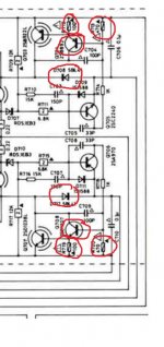
Here's a link to a schematic for the LH channel of this amp...just change each number by 50... (Q707 would be Q757 on RH channel...etc...)
http://www.diyaudio.com/forums/atta...offset-problem-nad-7250pe-offset-resistor.jpg
http://www.diyaudio.com/forums/atta...offset-problem-nad-7250pe-offset-resistor.jpg
OK
We need to do some very basic checks to get an idea of the state of play.
With the AMP OFF and unplugged.
1. Measure each of the four 0.22 ohm resistors on the emitters of the outputs and confirm that none are high or open circuit.
2. Measure using the diode range on your DVM across collector and emitter on all four output transistors. Although you are reading in circuit a short or almost short will show.
You can compare these readings with the other channel. Remember to keep the meter leads the same polarity when comparing one channel to the other.
3. I'm going to let YOU add 50 to the numbers because I don't know if that applies to all the passives as well. Check D708 and D712 for being short circuit. Again compare with other channel.
4. Check Q703 ??? (at the top) and Q707 for being short circuit C to E. EDIT I see you have found these as failed. These are used to switch a higher voltage rail to the output stage for maximum output power. However the amp should still function correctly with these either removed or short circuit. If short then the amp will run hotter than it should at all times. If removed then max power output will be lower.
So you have another problem beside these. Do the first checks I mentioned.
Those are the most basic of tests but must be done as a first step.
For ease of comparing to the schematic, I'm going to site all the RH components in the LH channel component numbers. Since we're all reading off the LH channel schematic.
Ok, so, one finding... While the amp was on end, and I was searching searching searching for D708/D712...I discovered under a bar a pot...the distortion pot for the RH channel. Elusive. I pulled it and found 1.4Mohms from end to end, should be 200ohms. So, I don't know if that would have much impact, but it's gotta be fixed.
I located D708/D712 and they both check good.
R640, R641, R642, and R643 (all the 0.22ohm output resistors) all check good.
Q616 and Q617 both check good as well.
I did find what may be a failure on Q618/Q619.
I lifted the emitter leg on all output transistors during test. Q618/Q619 both read OL when checking with + to C, and - to E, but 1.7v when checked - to C and + to E.
Q616/Q617 read OL when reading in either direction on the C and E terminals.
The 200 ohm pot (you mean the one at the top) is vital but could be replaced with a 100 ohm as shown. With it OC the amp will not function and you would get a huge offset. That offset would also cause the "rail switching" transistors to switch to the higher value... which you have got.
I would replace the resistor, then set the bias current pot (R624) to its HIGHEST resistance which will give the LOWEST quiescent current.
The transistors aren't reading short which would be the normal failure mode. You may just be reading via the circuitry still connected to the base. I would resolder them back and then using a bulb tester power the amp up and do a check of the vital voltages.
Output offset to be zero
The rails to be the lower value. That is to say Q707 and Q703 will have a higher voltage on the emitter than the collector such as 66 volts or so on E and maybe 45 (or whatever it uses) on C.
Well, it seems that the 200 ohm pot is going to be the culprit. I lifted all surrounding components to the failed transistors and found no issues, and when I lifted the other legs of the two suspects (Q618/619) I found them to be in good working order as well.
I will be ordering a couple of 100 ohm resistors to replace the POTs with. I'm thinking 1/4watt, but for safety's sake, I'm on edge of getting 1/2watt....
As for the comment about setting R624 to its highest resistance. I presume you mean full CCW... It would seem that CW would be lowest...
I will be holding off on applying any power until I get new transistors for Q703 and Q707, and the 100ohm resistors...
Right now I'm working on figuring out where to locate a D1238 and B922 transistor Or, at least...and alternate.
I will be ordering a couple of 100 ohm resistors to replace the POTs with. I'm thinking 1/4watt, but for safety's sake, I'm on edge of getting 1/2watt....
As for the comment about setting R624 to its highest resistance. I presume you mean full CCW... It would seem that CW would be lowest...
I will be holding off on applying any power until I get new transistors for Q703 and Q707, and the 100ohm resistors...
Right now I'm working on figuring out where to locate a D1238 and B922 transistor
Or, at least...and alternate.1/4 watt should be fine for the resistors.
For the transistors something like the MJL21193G and MJL21194G should be suitable. Slightly different package but will be a direct fit. Make sure they are the G suffix as these are the flatpak type.
Here's what I would do...
Just get and fit a couple of 100 ohm resistors.
Remove the failed transistors Q753 and Q757 and apply a shorting link between collector and emitter of each. This applies full rail voltage to the output stage.
Set the bias presets as mentioned. I never say CW or CCW because its open to interpretation. Set them so that they appear as if a 300 ohm resistor were fitted (the pot value) and not as a short (which they would be if turned the other way) In other words, Q609 needs to see the full 600 ohm between its base and emitter.
Using a bulb tester switch on (100 watt filament bulb in series with the mains). The bulb should go out after an initial flash. If so measure the DC voltage at the junction of the 0.22 ohms as before. Hopefully it will be near zero having replaced the faulty preset. If not we have a further problem that needs investigating.
I did as directed, and tadaaaa.... Relay clicked upon power up, and all parameters were adjustable! I was able to obtain 0.00mV for DC offset, and 9mV for idle current.
The bulb came on bright at first and dimmed down within 3 seconds.
I will look into replacement of the failed transistors and update once they're in.
I'm thinking perhaps I'll get 4, and replace the LH channel while I'm at it. I'll just consider it preventative maintenance.
The bulb came on bright at first and dimmed down within 3 seconds.
I will look into replacement of the failed transistors and update once they're in.
I'm thinking perhaps I'll get 4, and replace the LH channel while I'm at it. I'll just consider it preventative maintenance.
First of all, THANK YOU for everything you've helped me with. The repair was a success, the stereo tuned up perfectly. I currently have 0mV offset on both channels, and 9mV idle current on both channels.
The only thing that I am looking into clearing up is that now that I can get audio out to the speakers, I have mostly Mid and Treb with very little bass on the LH speaker, and mostly Bass and very little mid, and some treb out of the RH speaker.
This is true on either channel A or B....
I have noticed that some of the pushbuttons are a little intermittent, LowLevel and Loudness both seem like they could use some deoxit...
- Status
- This old topic is closed. If you want to reopen this topic, contact a moderator using the "Report Post" button.
- Home
- Amplifiers
- Solid State
- NAD 7250PE no service manual